


SB--7--622 Page 23
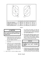
Replacement gears have minimum
backlash marks on the outside diame-
ter of the gear face. These marks
should be located 180 degrees from
each other (see FIGURE 23).
F.
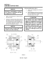
Position impellers so they are 90 degrees to
each other. Using the driving tool shown on
page 12, install the gears and hubs on the
shafts using the taper pin holes and match
marks for correct positioning. Check to be
sure impellers are in correct position as pre-
viously match marked.
Utilize a press whenever possible
when installing gears.
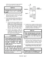
G. Refer to diagram in FIGURE 21, page 20.
Use feeler gauges to check clearances
between impeller lobes at positions A--A and
C--C. Add the clearances, and divide the total
clearance evenly between A--A and C--C.
H. Loosen the four capscrews (38) in one gear
only. Wedge the correct amount of feeler
gauge between the impeller at A--A. If move-
ment between the gear and hub is not suffi-
cient to time the impellers, it will be neces-
sary to loosen the four capscrews (38) in the
mating gear to obtain a large adjustment
range. Adjust so that the clearance at A--A
is equal to C--C within .001 inch.
Clearances must be checked on both sides
of each impeller lobe over the entire length.
This procedure may require repeating sever-
al times until impeller lobe clearance is equal
on both sides.
I.
Secure the timing gears (9) to the hubs (39)
with capscrews (38) and lockwasher (37).
Tighten capscrews to the torque specifica-
tion listed in FIGURE 24, page 24.
J.
Check gear backlash four places at 90
degree intervals as described in the disas-
sembly procedure (Item 4).
If any of the four gear backlash read-
ings are not within the specified
limits, the gears must be replaced.
K. Reream taper pin hole between the shaft and
hub with a hand reamer and replace taper pin
(8) if movement between the shaft and hub
(39) was negligible. If rereaming fails to elim-
inate edges due to slight misalignment, drill
and ream a new hole approximately 90
degrees from the original hole. Control the
depth of the taper pin, leaving approximately
1/8” taper pin protruding beyond the hub and
shaft.
L.
Reream center drilled hole in the hub and
gear web. If rereaming fails to eliminate
edges set up by retiming, ream hole for the
next larger taper pin or drill and ream a new
hole approximately 90 degrees from the orig-
inal hole. Control the depth of the threaded
taper pin (36), leaving the threaded portion of
the pin protruded beyond the hub.
Replacement gears are not drilled for taper
pin (8). These holes must be drilled and
reamed after the gears are in proper position
and the unit retimed.
Be careful not to allow cuttings to
drop behind the gears and contami-
nate the bearings.
M. Remove paper from behind the gears. Make
certain metal cuttings did not contaminate
the bearings.
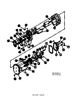
18. Assemble gear cover (3) and gasket (7) to the
gear headplate (18) using capscrews (5). Tighten
capscrews alternately and evenly.
Refer to
FIGURE 24, page 24 for torque specifications.
19. Place blower on its feet on a flat surface. Loosen
capscrews (16) and level unit up. The bench or
blower base flatness should be within .002 of an
inch. Re-tighten cap screws (16) to the specifica-
tions in FIGURE 24, page 24.
Summary of Contents for LEGEND GAF P Series
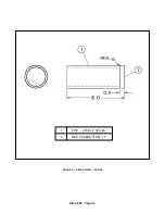
Page 19: ...SB 7 622 Page 12 1 PIPE STEEL 2 SCH 80 2 MED CARBON STEEL 1 2 FIGURE 9 GEAR DRIVER SK2150...
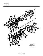
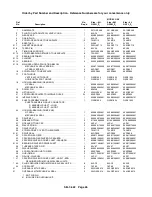
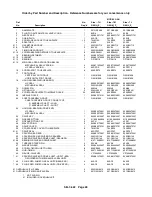
Page 32: ...SB 7 622 Page 25 SECTION 8 PARTS LIST 300GAF810 B Ref Drawing...
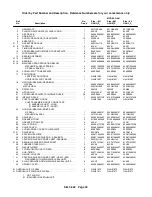
Page 34: ...SB 7 622 Page 27 300GAG810 A Ref Drawing...
Page 36: ...SB 7 622 Page 29 300GAH810 A Ref Drawing...
Page 39: ......


