GAMATRONIC,
A
S
OLAR
E
DGE
D
IVISION
Centric Installation Guide, rel. 4.7
39
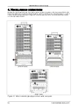
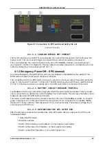
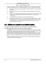
Figure 25: Connections for EPO switch and battery trip coil
(Connector Group 3)
4.1.1.1
LOAD-ON-BYPASS DRY CONTACT
The Centric includes a dry contact (“Load on Bypass” dry contact) that closes when the Centric goes into
bypass mode. This can be used to trigger an external circuit, such as an audible or visual alarm.
T
he “Load on Bypass” dry contact is located on the rear of the
Centric
controller, in connector group 3
(see Figure 21, and item 3 in Figure 25). This dry contact is normally opened (N.O.), and has two pins. The
contact is voltage free; it can accept up to 24 Vdc 1 A.
4.1.2 Emergency Power Off
– EPO (manual)
An external Emergency Power Off (EPO) switch may be installed on the
Centric
by the customer. The
EPO switch cuts power to the load in emergency situations.
The connection point for the EPO switch is a two-pin connector on the lower rear of the system (connector
group 3). See Figure 21, and item 1 in Figure 25. The EPO switch must be an N.O.-type, rated for at least
24 Vdc, 1 A. Be sure to perform a continuity test on the EPO switch before connecting it to the UPS.
4.1.2.1
BATTERY CIRCUIT BREAKER TRIPCOIL
The
Centric
includes a dry contact that closes when the EPO switch has been activated. This dry contact
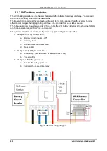
can be connected to an optional trip coil on the battery box circuit breaker. This will cause the battery circuit
breaker to open when the EPO switch is activated.
The battery circuit breaker trip coil dry contact is located on the rear of the
Centric
controller, in connector
group 3 (see Figure 21), to the right of the EPO connector (see item 2 in Figure 25). It is labelled "Battery
CB trip coil". The dry contact is “normally opened” (N.O.), and has two pins. The contact is voltage free; it
can accept up to 230 Vdc 2 A.
4.1.2.2
RESTARTING THE UPS AFTER EPO
After the emergency situation that prompted use of the EPO switch has been resolved, the UPS can be
restarted as follows:
1. Reset the EPO switch.
2.Wait three minutes.
3.Switch off the following circuit breakers: ac input, bypass input, battery.
4.Switch on the same circuit breakers: ac input, bypass input, battery.
5.Switch on
the UPS (“Operation > Turn on/off > System on”).

