


Hand drilling of orifices is never acceptable since it
could lead to delayed ignition, overfiring, improper
combustion, flashback and flame rollout. All these
conditions could lead to a fire hazard and bodily
harm, or loss of life.
Blower Adjustment Checkout:
This furnace is equipped with a variable speed
circulation air blower motor that will deliver a constant
airlfow within a wide range of external static pressures.
The unit as shipped is factory set to run at the middle of
the heating rise range as shown on the unit rating plate.
For low heat to high heat transition the control
changes the blower speed from low heat speed to high
heat speed. Check the temperature rise between the
return and supply plenums to make sure it is within the
rise range shown on the rating plate.
Heat blower off delay is a fixed 180 second delay.
After the 180 second delay the motor will slowly ramp
down to a soft stop. N0 adjustments need to be made in
the heating mode.
Limit Control Checkout:
After the furnace has been in operation for at least 15
minutes, restrict the return air supply by blocking the
filters or closing the return registers and allow the furnace
to shut down on high limit. The main burners will shut
OFF and the main blower and combustion blower should
continue to run. Remove the restriction and the burners
should come back on in a few minutes.
Flame Rollout Switch:
This unit is equipped with a manual reset flame-rollout
switch that protects against improper venting of the flue
gases from the heat exchanger due to blockage causes
heat (or flames) to "rollout" into the burner box from the
heat exchangers, this safety device will activate and shut
off power to the automatic gas valve before there is
damage to the furnace. The loss of power to the gas
valve will shut off the gas burners. Should this occur, it
will be necessary to determine the cause of the rollout,
correct the condition that caused it, and reset the flame-
rollout switch.
The furnace should be allowed to cool-off before
attempting to reset the switch. Failure to follow
these instructions could result in injury due to burns!
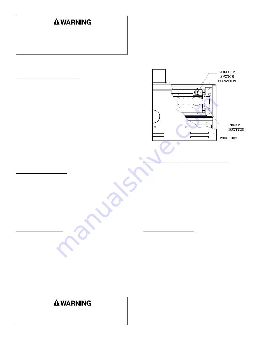
The switch is located behind the burner access door.
Removing the burner access panel from the furnace, and
reset by pushing in the button in the middle of the switch
(between the two wire connections - See Figure 31).
Very little force is required to push the reset button, and
a "click" should be heard when the switch resets.
Figure 31
FLAME ROLLOUT SWITCH
Blocked Vent & Drain Pressure Switchs:
This furnace is equipped with two pressure switches
that performs several safety functions. The pressure
switches are located in the vestibule of the unit (See
Figure 32). The pressure switch will turn the burners
OFF in the event of a blocked air inlet or a blocked flue
outlet condition. The pressure switch will also turn OFF
the burners in the event of a blocked drain condition. The
pressure switch also insures that the unit has combustion
air flowing through the unit prior to initiating the ignition
sequence.
Pressure Switch Check:
To check the operation of the pressure switch
combustion air control, remove the inlet pipe from the air
inlet connector and remove the street sweep elbow from
the induced draft motor vent outlet coupling. Place the
furnace into operation for high fire. Gradually cover up
the air inlet; the furnace should first drop to low fire and
with further restriction of the opening, the main burners
should shut OFF. Remove the restriction and the unit
should relight. Repeat the procedure, restricting the vent
coupling outlet. Replace the vent piping and reseal the
opened joints as required. To check the operation of the
blocked drain, place the unit into operation and gradually
pinch the tube running from the condensate trap to the
pressure switch closed. The unit should shut OFF.
Release the restriction on the tubing and the unit should
relight.
The operational checkout is now complete. Be sure
to adjust the thermostat to the desired setting and inform
20558801
Issue 0442
Page 26 of 32
Summary of Contents for Gas-Fired Furnace
Page 13: ...FURNACE WIRING SPECIFICATIONS 20558801 Issue 0442 Page 5 of 32 ...
Page 21: ...Figure 8 20558801 Issue 0442 Page 13 of 32 VENT TERMINATION CLEARANCES ...
Page 36: ...SEQUENCE OF OPERATION DIRECT IGNITION SYSTEM CONTROL 20558801 Issue 0442 Page 28 of 32 ...
Page 40: ...WIRING DIAGRAM 20558801 Issue 0442 Page 32 of 32 ...


