background image


- 21 -

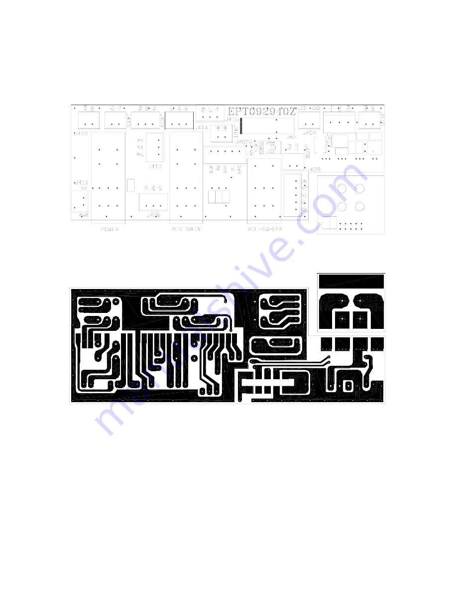
DX 929 (POWER/MIC GAIN/VOL-SQ CONTROL) VR PCB  

(EPT092940Z) 


( COMPONENT SIDE )


( COPPER SIDE ) 


Summary of Contents for DX 929

Page 1: ...CB Radio Model DX 929 Service Manual Copyright Reserved...

Page 2: ...phones And Installation 8 CHAPTER 3 CIRCUIT DESCRIPTION 3 0 Introduction 9 3 1 PLL Circuit 9 3 2 Receiver Circuit 9 3 3 Transmitter Modulation Circuit 9 3 4 Transmitter Amplifier Circuit 9 CHAPTER 4 A...

Page 3: ...0 Hz Antenna Impedance 50 Ohms Output Indicators Meter shows incoming signal strength RF output power SWR and AM Modulation level Transmit LED glows red when transmitter is in operation 1 2 RECEIVER S...

Page 4: ...er To use this feature turn the knob fully counterclockwise and then turn clockwise slowly until the background noise is just eliminated Further clockwise rotation will increase the threshold level wh...

Page 5: ...CH This switch controls the function of the meter during the transmit mode In the SWR position the meter indicates the Standing Wave Ratio SWR of your antenna There are no adjustments because the SWR...

Page 6: ...aker 8 ohms 4W to this jack 4 EXT SP This jack accepts a 4 to 8 ohm 5 watt external speaker When the external speaker is connected to this jack the built in speaker will be disabled 5 F C This jack is...

Page 7: ...255 4 27 005 24 27 235 5 27 015 25 27 245 6 27 025 26 27 265 7 27 035 27 27 275 8 27 055 28 27 285 9 27 065 29 27 295 10 27 075 30 27 305 11 27 085 31 27 315 12 27 105 32 27 325 13 27 115 33 27 335 14...

Page 8: ...wer to the radio 3 Set the VOL to a comfortable listening level 4 Set the MODE switch to the desired mode 5 Listen to the background noise from the speaker Turn the SQUELCH knob slowly clockwise until...

Page 9: ...lead cable The audio conductor and its shielded lead comprise two of the leads The third lead is for transmit control and the fourth is for receiving control The microphone should provide the function...

Page 10: ...R CIRCUIT The incoming RF signal comes into the radio via the antenna and into the front end pre amp Q17 The RF signal is fed into the mixer circuit of Q18 Q19 and then into the AM IF section of the r...

Page 11: ...10...

Page 12: ...used for the test setup or alignment shown in Figure 4 1 Transmitter Test Setup and Figure 4 2 Receiver Test Setup These test setups are used in part or total during the following adjustments Refer to...

Page 13: ...l 30mV 1 KHz to microphone Set MIC Gain fully clockwise VR15 For a needle reading of 90 on the modulation scale 4 1 3 RECEIVER ALIGNMENT ITEM U U T SETTING ADJUST POINT MEASUREMENT AM Sensitivity Set...

Page 14: ...13 Figure 4 1 Transmitter test setup Figure 4 2 Receiver test setup...

Page 15: ...14 DX 929 MAIN PCB ADJUSTMENT LOCATION RF METER AM MOD AM LOW POWER AM HI POWER AM MOD METER AM S METER AM SQUELCH 10 240 MHz ADJUST AM LOW POWER AM MOD...

Page 16: ...pection and maintenance Important points to be checked regularly are as follows Check Item Action Whip antenna option If cracked or broken replace it Coaxial cable If sheath is cracked or immersed in...

Page 17: ...16 DX 929 CHAPTER 6 DIAGRAMS PARTS LIST 6 0 GENERAL Information on most electrical and mechanical parts is included in the parts list The reference designators are in alphanumeric order...

Page 18: ...17 DX 929 ROTARY SWITCH PCB EPT092920Z SMD COPPER SIDE COMPONENT SIDE...

Page 19: ...C201 C202 CK1104AB5X CHIP C 0 1uF 50WV 10 D201 D202 D203 D204 D205 D206 D207 D208 D209 D210 D211 D212 D13 D214 D215 D216 D 217 D218 D219 D220 D 226 D227 D228 EDSS00355Y DIODE S M D 1SS355 11 D221 D222...

Page 20: ...19 DX 929 DISPLAY PCB EPT092930Z COMPONENT SIDE COMPONENT SIDE COPPER SIDE...

Page 21: ...R304 R305 R306 RCY016814Z CHIP F R 680 0 1W 3 R308 RCY011024Z CHIP F R 1K 0 1W 4 R310 RCY012224Z CHIP F R 2 2K 0 1W 5 R309 RCY012234Z CHIP F R 22K 0 1W 6 D301 D302 EDSS00355Y DIODE 1SS355 7 LED201 LED...

Page 22: ...21 DX 929 POWER MIC GAIN VOL SQ CONTROL VR PCB EPT092940Z COMPONENT SIDE COPPER SIDE...

Page 23: ...CHIP C 01uF 50VW 6 L402 YCTLI5653C CHOKE COIL 5 6uH 7 L401 YCBAD18581 BEAD FERRITE COIL WB 403025 8 Q902 TYDTA124EA T R DTA124EUAT106 9 MIC GAIN RV10203529 VR 1KA 10 VOL SQ OFF RV50303522 V R 50KB 50...

Page 24: ...PPER SIDE PART LIST DX 929 RF GAIN DIMMER CONTROL VR P C B ITEM REFERENCE NUMBER RANGER PART NUMBER DESCRIPTION 1 EPT092950Z TB PCB 2 VR501 DIMMER RV50203525 VR 5KB 3 VR502 RF GAIN RV10203528 VR 1KB 4...

Page 25: ...24 DX929 METER PCB EPT092961Z COMPONENT SIDE COPPER SIDE COPPER SIDE SMD...

Page 26: ...IP C 0 1uF 50WV 10 C619 CK5105AB7R CHIP C 1uF 16WV 11 C621 CK1473AB5X CHIP C 0 047uF 50WV 12 C617 CK2474AB7R CHIP C 0 47uF 25WV 13 C605 C611 CK5475AA7R CHIP C 4 7uF 16WV 14 C622 CTY161066A T C 10uF 16...

Page 27: ...W 5 R2 RCY013314Z 330 OHM 0 1W 6 R5 R11 RCY011024Z 1K OHM 0 1W 7 R10 R12 RCY012224Z 2 2K OHM 0 1W 8 R7 C5 RCY011034Z 10K OHM 0 1W 9 C7 CK1059AB1A 0 5PF 50WV 10 C6 CK1030AB1A 3PF 50WV 11 C3 C4 CK2104AB...

Page 28: ...27 DX 929 MAIN PCB EPT092913Z COMPONENTS SIDE...

Page 29: ...28 DX 929 MAIN PCB EPT092913Z COPPER SIDE...

Page 30: ...9 RCP121034Z 10K 1 2W C8 CC0508204L 82PF 50WV C4 CC0501015L 100PF 50WV C137 CC0501515L 150PF 50WV C31 136 CC0502715L 270PF 50WV C11 14 CC0503315L 330PF 50WV C23 CC0505615L 560PF 50WV C52 197 CC0500101...

Page 31: ...CIFT12253 I F T L5 ECIFT12440 I F T L8 ECIFT12492 I F T L48 ECCHK16096 470UH L503 ECCHK16000 0 47UH T1 ECCHK16004 1 1MH EI 19 L33 37 ECCHK16070 22UH L47 ECCHK16176 4 7UH L16 ECCHK16246 22UH L30 ECSPG1...

Page 32: ...DX 929 SCHEMATIC DIAGRAM CONTROL PCB...

Page 33: ...DX 929 SCHEMATIC DIAGRAM MAIN PCB...

Page 34: ...DX 929 MECHANICAL PART DX 929 EXPLODE DRAWING...

Page 35: ...Any updates or corrections to this Service Manual will be included in the Tech Support section of our website at www GalaxyRadios com UPDATES CORRECTIONS...

Page 36: ...ber RAN This RAN may be obtained from our website or by calling our Service Department at 760 480 8800 between 10 00 AM and 4 00 PM Pacific Time The RAN must be written below your return address on th...

Page 37: ...ATS929010A July 2003...

Reviews: