- 5 -
REAR PANEL
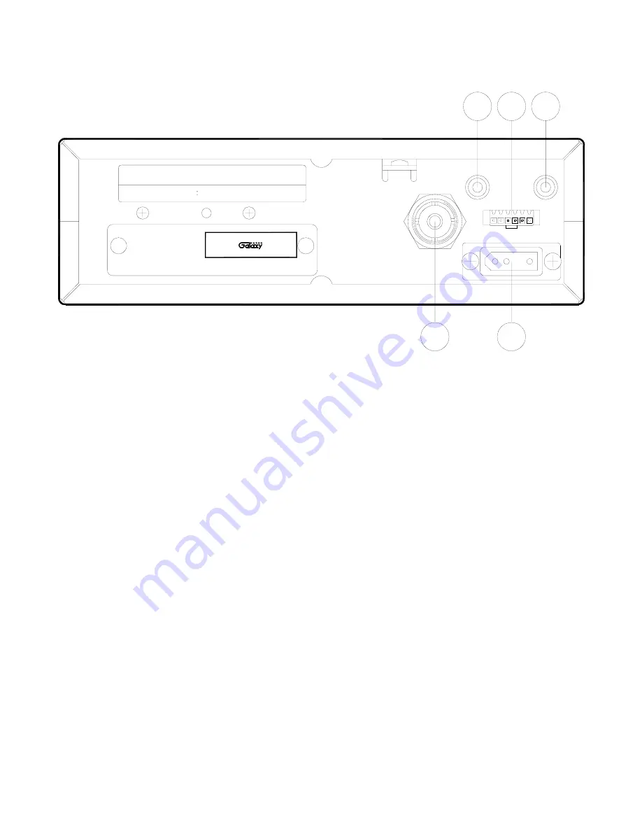
Figure 2-2 represents the location of the following connections:
Figure 2-2 Rear Panel
1. ANTENNA:
This jack accepts a 50-ohm coaxial cable with a PL-259 type plug.
2. DC POWER:
This jack accepts the 13.8V DC power cable with built-in fuse. The power cord
provided with the radio has a black and red wire. The black goes to negative and red goes to
positive.
3. PA SP.:
This jack is for PA operation. Before operating, you must first connect a PA speaker (8
ohms, 4W) to this jack.
4. EXT SP.:
This jack accepts a 4 to 8 ohm, 5-watt external speaker. When the external speaker is
connected to this jack, the built-in speaker will be disabled.
5. F
.
C
.
:
This jack is used to connect the optional Galaxy FC347 six-digit frequency counter. All
connections, including DC power, are provided to the FC347 through this jack.
SERIAL NO. :
FCC ID : MEE − DX − 929
DATE OF MFG.:
AM 40 CH
CB TRANSCEIVER
MODEL NO. : DX 929
- DC 13.8V +
PA SP.
ANT
F.C.
EXT SP.
1
2
4
3
5
This device complies with part 15 of the FCC Rules.
Operation is subject
to the condition that this device does not cause harmful interference.
Service Manual at www.GalaxyRadios.com
Summary of Contents for DX 929
Page 1: ...CB Radio Model DX 929 Service Manual Copyright Reserved...
Page 11: ...10...
Page 14: ...13 Figure 4 1 Transmitter test setup Figure 4 2 Receiver test setup...
Page 18: ...17 DX 929 ROTARY SWITCH PCB EPT092920Z SMD COPPER SIDE COMPONENT SIDE...
Page 20: ...19 DX 929 DISPLAY PCB EPT092930Z COMPONENT SIDE COMPONENT SIDE COPPER SIDE...
Page 22: ...21 DX 929 POWER MIC GAIN VOL SQ CONTROL VR PCB EPT092940Z COMPONENT SIDE COPPER SIDE...
Page 25: ...24 DX929 METER PCB EPT092961Z COMPONENT SIDE COPPER SIDE COPPER SIDE SMD...
Page 28: ...27 DX 929 MAIN PCB EPT092913Z COMPONENTS SIDE...
Page 29: ...28 DX 929 MAIN PCB EPT092913Z COPPER SIDE...
Page 32: ...DX 929 SCHEMATIC DIAGRAM CONTROL PCB...
Page 33: ...DX 929 SCHEMATIC DIAGRAM MAIN PCB...
Page 34: ...DX 929 MECHANICAL PART DX 929 EXPLODE DRAWING...
Page 37: ...ATS929010A July 2003...


