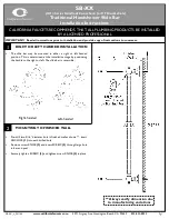
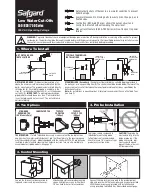
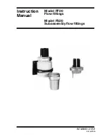
Unscrew the two top and bottom retaining
screws
(Fig.5)
and lift the cover from the
backplate. NOTE: Deviations from the
designated entry points will invalidate
product approvals.
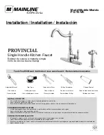
required for the Cold water pipe, then a
aperture will need to be cut out of the
cover
(Fig.7)
and the inlet elbow rotated
to face downward.
If entry is required from the back, rotate
the inlet elbow upwards and fit elbow to
connect to the pipe
(Fig.8)
. Ensure the
hole in which the pipe enters through the
wall is filled in completely in order to
Fig.5
Fig.6
If a top entry is required for the water pipe,
remove the blanking plug in the backplate
(Fig.6)
and ensure the inlet elbow so that
It points upward. If a bottom entry is
Fig.7
Bottom Entry
Aperture
‘Cut-Out’
W
ALL
87 mm
28.5 mm
19 mm
Fig.8
prevent any possible ingress of water into
the cavity area. After choosing the site for
the shower, use the supplied template and
mark the three fixing holes
(Fig.9)
. Drill
and plug to suit the fixing screws supplied.
(The wallplugs provided are suitable for
most brick walls – use an appropriate
masonry drill, but if the wall is
plasterboard or a soft building block, you
must use special wallplugs and an
appropriate drill obtainable from most
hardware stores).
Fig.15
Spindle in
COLD
position
Flat
Fig.12
Fig.14
Element(s) to burn out and invalidate
the guarantee.
The first operation of the shower is
intended to flush out any remaining unit
debris, and to ensure the heater unit
contains water before the elements are
switched on.
This operation must be carried out with
the flexible hose (supplied) screwed to the
outlet but
without
the sprayhead attached.
Ensure the outlet of the flexible hose is
directed to waste and ensure the end of
the hose is below the shower unit.
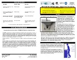
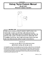
To ensure the temperature control is
correctly positioned on the stabilising
valve, temporarily place the cover in
position so that the splines engage then
rotate the temperature control knob fully
Anti-clockwise.
Remove the cover and position the
temperature control so that it points
towards ‘TEMPERATURE’
(Fig.13)
.
Position the power selector to the 'COLD'
position
(Fig.12)
.
Ensure power selector is in Cold position
(Fig.14)
before continuing.
Ensure the water supply is still turned on
to the shower.
Open the bleed screw adjacent the rubber
hose
(Fig.15)
by rotating anti-clockwise
slowly until water flows from the drain pipe,
this indicates that any trapped air is
vented and that the pump unit is primed.
The bleed valve must now be closed by
rotating clockwise.
DO NOT
OVERTIGTHEN.
Attach to the stop/start switch inside the
cover is a power lead. The socket on the
end of this lead must be connected to the
plug that is situated near the top of the
backplate unit
(Fig.16)
.
NOTE:
The plug
and socket can only fit one way.
Offer the cover to the backplate unit.
Ensure the power selector is still at the
Bleed Screw
(’XP’ Model)
Fig.13
Fig.12