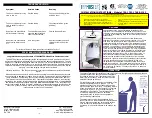
Products manufactured by Galaxy are
safe and without risk provided they are
installed, used and maintained in good
working order in accordance with our
instructions and recommendations.
DO NOT
connect this shower directly
to the mains water supply.
DO NOT
operate shower if frozen, or
suspected of being frozen. It must
thaw out before using.
DO NOT
operate the unit if the spray-
head or spray hose becomes
damaged.
DO NOT
restrict flow out of the
shower by placing sprayhead in direct
contact with your body.
DO NOT
operate the shower if water
ceases to flow during use or if water
has entered inside the unit because
of an incorrectly fitted cover.
WARNING:
If re-starting the shower
immediately after stopping, be aware
that a slug of hot water will be
expelled for the first few seconds.
GENERAL
1.
Isolate the electrical and water supplies before
removing the cover.
2.
Read all of these instructions and retain them for
later use.
3.
DO NOT take risks with plumbing or electrical
equipment.
4.
Isolate electrical and water supplies BEFORE
proceeding with the installation.
5.
The unit must be mounted onto the finished wall
surface (on top of the tiles). DO NOT tile up to unit
after fixing to wall.
6.
Contact Customer Service (see back page),
if any of the following occur;
a
) If it is intended to operate the shower at pressures
above the maximum or below the minimum stated.
b
) If the unit shows a distinct change in performance.
c
) If the shower is frozen.
7.
If it is intended to operate the shower in areas of
hard water (above 200 ppm temporary Hardness), a
scale inhibitor may have to be fitted.
8.
The sprayplate and cartridge must be
cleaned
regularly with descalent to remove scale and debris,
otherwise restrictions to the flow on the outlet of the
unit will result in higher temperatures and could also
cause the Pressure Relief Device in unit to operate.
9.
This product is not suitable for mounting into
steam rooms or steam cubicles.
PLUMBING
1.
The plumbing installation must comply with Water
Regulations, Building Regulations or any particular
regulations as specified by Local Water Company or
Water Undertakers and should be in accordance with
BS 6700.
2.
The supply pipe must be flushed to clear debris
before connecting to shower unit.
3. DO NOT solder pipes or fittings within 300mm of
shower, as heat transfer can damage components.
4.
DO NOT fit any form of outlet flow control as
the outlet acts as a vent for the heater can.
5.
DO NOT use excessive force when making
connections to the flexible hose or sprayhead, finger
tightness is sufficient.
6.
Al plumbing connections MUST be completed
BEFORE making the electrical connections
.
ELECTRICAL
1.
The installation must comply with BS 7671
Requirements for electrical installations’ (IEE wiring
regulations) or any particular regulations as specified
by the local Electrical Supply Company.
2.
This appliance MUST be earthed.
3.
In accordance with ‘The Plugs and Sockets etc.
(Safety) Regulations 1994’, this appliance is
intended to be permanently connected to the fixed
wiring of the electrical mains system.
4.
Ensure all electrical connections are tight to
prevent overheating.
5.
Fuses do not give personal protection against
electric shock.
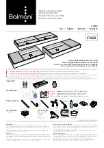
PACK
CONTENTS
1
SECTION
PACKING CONTENTS
PACK
CONTENTS
2
SECTION
PLEASE READ THIS IMPORTANT
SAFETY INFORMATION
Shower Unit
Showerhead
Showerhead Key
Flexible Hose
Slider Rail Tube
Slider Rail Brackets
Slider Rail Showerhead Holder
Soap Dish
Hose Retaining Ring
Screw Pack
18
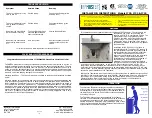
SECTION
FILTER MAINTENANCE
INSTRUCTIONS for INSTALLERS
and SERVICE ENGINEERS
It is recommended that the filter is
periodically cleaned in order to maintain
the performance of the shower.
It is
essential that this operation is carried out
by a competent person.
SWITCH OFF THE ELECTRICITY
SUPPLY. There is no need to turn off the
mains water supply when cleaning the
filter.
Remove the cover and disconnect the
plug.Turn off the water supply to the unit
by rotating the lever on top of the filter
service shut off valve
(Fig.21)
anti-
clockwise a quarter turn.
Filter Service
Shut-Off
Valve
Do not rely on the filter service shut off
valve when carrying out repairs or service
to other areas of the shower unit.
Unscrew the three screws in filter cover
(Fig.22)
remove cover.Take out filter
and
wash under running water. Ensure all
debris etc. is removed.
Replace filter. Replace cover ensuring all
three screws line up. Replace the three
screws.
DO NOT OVERTIGHTEN.
Fig.21
Turn unit water supply back on by rotating
the lever on top of the filter service shut
off valve clockwise a quarter turn.
Before replacing the cover, it is strongly
advised to prime the unit by opening the
bleed screw until water drains from it.
Close the bleed screw and connect the
plug to the cover. Replace the cover and
secure with the fixing screws.
Switch on the electric supply and start the
shower on the
COLD SETTING ONLY
and with the temperature control rotated
fully anti-clockwise.
When a smooth flow of water is obtained,
the shower can then be used in the
Normal manner.
Filter Cover
Screws
ATTENTION!
NOTE: IN NORMAL USE, IT IS IN
ORDER TO LEAVE THE WATER
SUPPLY PERMANENTLY ON TO THE
SHOWER UNIT, BUT AS WITH MOST
ELECTRICAL APPLIANCES,
THE
UNIT MUST BE SWITCHED OFF
AT THE ISOLATING SWITCH
WHEN NOT IN USE.
Fig.12
Fig.22