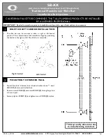
Screw the two upper fixing screws into
position leaving the base of the screw
heads protruding 6mm (0.25in) out from
the wall. Hook the backplate over the top
screws and fit the lower fixing screw into
position. DO NOT fully tighten the screws
at this stage, as the fixing holes are
elongated to allow for out of square
adjustment after the plumbing connections
have been completed.
10
SECTION
PLUMBING CONNECTIONS
PLUMBING TO PRECEDE WIRING
WARNING:
The outlet of the shower acts
as a vent and must not be connected to
anything other than the hose and
sprayhead supplied.
GALAXY ‘AQUA 9000 XP’
FIXING TEMPLATE
V
E
R
TI
C
AL
C
EN
T
R
E
L
IN
E
HORIZONTAL CENTRE LINE
Fig.9
DO NOT
use jointing compounds on
any pipe fittings for the installation.
DO NOT
use soldered fittings within
the vicinity of the shower unit.
NOTE:
An additional gate valve or fullway
lever valve must be fitted in the water
supply to the shower as an independent
means of isolating the water supply should
maintenance or servicing be necessary.
IMPORTANT:
The fitting on the inlet elbow
is a push-in type. The pipework must be
cut with a pipe cutter and all burrs and
rough edges removed from the end of the
tube. The fitting can be used with copper
and plastic pipe. If using chrome plated
copper pipe, remove the first 25mm of
plating completely from the connecting
surface. If it is not completely removed
then the collet will not grip the pipe and
under pressure the pipe may be forced
out.
CONNECTION PROCEDURE: Turn off
water supply either at the mains stopvalve
or the isolating stopvalve to the cistern.
Drain the cistern.
IMPORTANT:
T
he pipework must be
brought direct from the Cold water storage
cistern with no other Cold water draw offs
between the shower and the cistern.
IMPORTANT: Before completing the
connection of the water supply to the
inlet of the shower, flush out the
pipework to remove all swarf and
system debris. This can be achieved by
connecting a hose to the pipework and
turning on the water supply long
enough to clear the debris to waste.
Fit the pipework to the inlet elbow. Ensure
the elbow collet is fully engaged with the
pipe. Although the pipework connection to
the shower is via 15mm diameter
pipework, on long runs use 22mm
diameter piping as far as possible to avoid
restricting the flow to the shower.
Ensure that the backplate of the unit is flat
on the wall and positioned squarely.
Tighten the fixing screws.
Turn on the water supply and check for
leaks in the pipework connection to the
shower.
NOTE:
At this stage no water can
flow through the unit.
11
SECTION
ELECTRICAL
CONNECTIONS
SWITCH OFF THE ELECTRICITY
SUPPLY
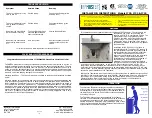
The cable entry points are shown in
(Fig. 10).
The cable can be surface clipped, hidden
Or via 20mm conduit. NOTE: Metal
conduit entry can only be from rear.
Route the cable into the shower unit and
connect to the terminal block
(Fig. 11)
As
Follows:-
Earth cable to terminal marked ......
Neutral cable to terminal marked ...
N
Live cable to terminal marked.........
L
E
IMPORTANT: Fully tighten the terminal
block screws and ensure that no cable
insulation is trapped under the screws.
Loose connections can result in cable
Overheating.
.
Fig.11
NOTE: The supply cable earth conductor
must be sleeved. The outer sheath of the
supply cable must be stripped back to the
minimum. The supply cable must be
secured either by routing through conduit
or in trunking or by embedding in the wall,
in accordance with current IEE regulations.
The use of connections within the unit, or
other points in the shower circuit, to
supply power to other equipment i.e.
extractor fans, pumps etc. will invalidate
the guarantee.
DO NOT switch on the electricity
supply until the cover has been fitted.
Fig.10
12
SECTION
COMMISSIONING
DO NOT switch on the electricity
supply until the following procedure
has been completed and the cover has
been fitted. Failure to do so could
Cause the pump to run dry and
invalidate the guarantee.
Cold position must be selected on
power selector (Fig.14) Before carrying
out any of the steps below. Failure to
do so
WILL
cause the heating