Twin and Earth PVC Insulated Cable
CURRENT CARRYING CAPACITY
Installed in an
Insulated
Wall
In Conduit or
Trucking
Clipped
Direct or
Buried in a
non Insulated
Wall
6mm2
6mm2
6mm2
32A
38A
46A
10mm2
10mm2
10mm2
43A
52A
63A
16mm2
16mm2
16mm2
57A
69A
85A
Note: Cable selection is dependent on de-rating factors
CIRCUIT PROTE CTION
Unit
Rating
MCB
Cartridge
Fuse
7.0kW
30/32A
30A
7.5kW
32A
35A
8.0kW
40A
35A
8.5kW
40A
45A
9.0kW
40A
45A
9.5kW
40/45A
45A
10.5kW
45A
45A
appliances and services in the room in
which the shower is to be installed, to
conform to current IEE regulations.
11.
All exposed metallic parts in the
bathroom must be bonded together
using a cable of at least 4mm2 cross
sectional area. These parts include
metal baths, radiators, water pipes,
taps and waste fittings.
12.
For close circuit protection
DO NOT
use a rewireable fuse. Instead use a
suitably rated miniature circuit breaker
(MCB) or cartridge fuse
(See table A)
.
13.
In the interest of electrical safety a
30mA residual current device (RCD)
should be installed in all UK electric
and pumped shower circuits.This may
be part of the consumer unit or a
separate unit.
14.
A 45 amp double pole isolating switch
with a minimum contact gap of 3mm
in both poles must be incorporated in
the circuit.
15.
It must have a mechanical indicator
showing when the switch is in the OFF
position, and the wiring must be
connected to the switch without the
use of a plug or socket outlet.
16.
The switch must be accessible and
clearly identifiable, but out of reach of
a person using a fixed bath or shower,
except for the cord of a cord operated
switch, and should be placed so that it
is not possible to touch the switch
body while standing in a bath or
shower cubicle. It should be readily
accessible to switch off after using the
shower.
17.
Where shower cubicles are located in
any rooms other than bathrooms, all
socket outlets in those rooms must be
Protected by a 30mA RCD.
18.
The current carrying capacity of the
cable must be at least that of the
shower circuit protection
(See table
B).
.19.
To obtain full advantage of the power
provided by the shower, use the
shortest cable route possible from the
consumer unit to the shower.
20.
It is also necessary to satisfy the
disconnection time and thermal
constraints which mean that for any
given combination of current demand,
voltage drop and cable size, there is a
maximum permissible circuit length.
21.
The shower circuit should be
separated from other circuits by at
least twice the diameter of the cable
or conduit.
22.
The current rating will be reduced if
the cabling is bunched with others,
surrounded by thermal loft or wall
insulation or placed in areas where the
ambient temperature is above 30°C.
Under these conditions, de-rating
factors apply and it is necessary to
Tabel ‘A’
Tabel ‘B’
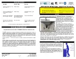
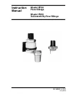
1. To start the shower
Pressing the start/stop button
(Fig.19)
switches on the pump allowing water to
immediately flow through the unit.
2. To stop the shower
Press the start/stop button. This initiate
the Phased (Safety) Shutdown feature.
The Phased (Safety) Shutdown feature
lasts for approx 8 seconds, during which,
the indicator light will flash ON & OFF, the
flow of water will be reduced and the
power to the heating elements cut. This
allows the unit to safely flush out any
residual heat. After which the pump
switches off and the water flow will cease
.
WARNING: If re-starting immediately
after stopping, be aware that a slug of
HOT water will be expelled for the first
few seconds.
3. To use the power selector
The power selector
(Fig.19a)
has four
settings – Cold, Low, Medium and Full
power.
‘Cold’
setting
(Solid Blue Symbol):
Is Cold water only. Adjustment at
the temperature control at this
setting will only increase or
decrease the force of the water
from the sprayhead.
It will not alter
The water temperature.
‘Low’
setting
(Outline Red Symbol):
Is the low setting for extra economy
during hot months. Temperature
adjustment at this setting is via the
temperature control.
‘Medium’
setting
(Solid Red Symbol):
Is the medium setting for economy
during warmer months and any
temperature adjustment at this
setting is via the temperature
Control.
:
Fig.19
Start/Stop
Button
Power
Selector
Temperature
Control
Fig.19b
COOLER
WARMER
COLD
HIGH
MEDIUM
Fig.19a
LOW