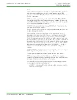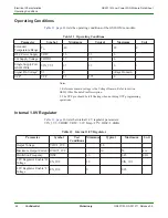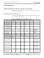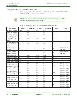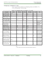
Pin-out and Signal Description
GS2011M Low Power WiFi Module Data Sheet
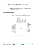
GS2011Mxx Device Pin-out
40
Confidential
Preliminary
GS2011M-DS-001211, Release 0.9
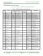
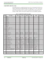
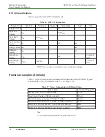
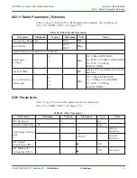
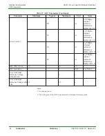
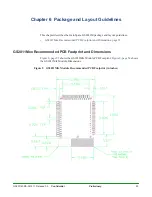
35
GPIO26/
UART1_CTS
VDDIO
Pull-down
4
Digital
Input/Output
GPIO/UART1Clear to Send
input (see Note 6)
36
GPIO27/
UART1_RTS
VDDIO
Pull-down (see Note 2)4
Digital
Input/Output
GPIO/UART1 1 Request to
Send Output (see Note 6).
This pin is used for Program
Mode.
37
GPIO3/
UART1_RX
VDDIO
Pull-down
4
Digital
Input/Output
GPIO/UART1 Receive
Input
38
GPIO32/
SDIO_DAT2/
UART1_TX
VDDIO
Pull-down
4
Digital
Input/Output
GPIO/SDIO_DATA Bit
2/UART 1 Transmitter
Output
39
GPIO1/
UART0_TX
VDDIO
Pull-down
4
Digital
Input/Output
GPIO/UART0 Transmitter
Output. This pin is used for
Code Restore.
40
GPIO25/
UART0_RTS
VDDIO
Pull-down
12
Digital
Input/Output
GPIO/UART0 Request to
Send Output (see Note 6).
This pin is used for Program
Select.
41
GPIO0/
UART0_RX
VDDIO
Pull-down
4
Digital
Input/Output
GPIO/UART0 Receive
Input
42
GPIO24/
UART0_CTS
VDDIO
Pull-down
12
Digital
Input/Output
GPIO/UART0 Clear to
Send Input (See Note 6)
43 GPIO31/PWM2
VDDIO
Pull-down
16
(see Note 7)
Digital
Input/Output
GPIO/Pulse Width
Modulation Output 2
44 GPIO30/PWM1
VDDIO
Pull-down
16
(see Note 7)
Digital
Input/Output
GPIO/Pulse Width
Modulation Output 1
45 GPIO29/I2C_CLK VDDIO
Pull-down
12
Digital
Input/Output
GPIO/I2C_CLK (see Note
3)
46
GPIO37/
SDIO_DAT1_INT
VDDIO
Pull-down (see Note 9)4
Digital
Input/Output
GPIO/4-bit SDIO DATA bit
1/SDIO SPI Mode Interrupt
47
EXT_RESET_n
(see Note 5)
VDDIO
Digital Open
Drain
Input/Output
Module Hardware Reset
Input and Power Supply
Reset Monitor Indicator
Active Low
48 GND
0V
Not Applicable
Analog port
Ground
49 VPP (see Note 8) VPP
Analog port
Programming Voltage for
OTP Memory
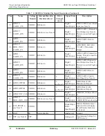
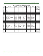
Table 7 GS2011Mxx Module Pin Signal Description (Continued)
Pins
Name
Voltage
Domain
Internal Bias after
Hardware Reset
Drive
Strength
(mA)
Signal State
Description

