P
UB
.
42004-441H
H
ANDS
-
FREE
V
O
IP
T
ELEPHONE
M
ANUAL
P
AGE
20
OF
28
P:\Standard IOMs - Current Release\42004 Instr. Manuals\42004-441H.docx
07/16
I/O
Inputs
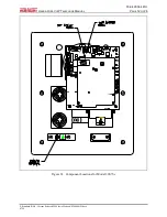
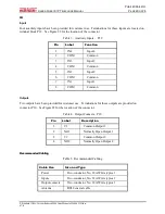
Four auxiliary inputs have been provided for customer use. Terminations for these inputs are located on
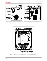
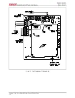
terminal block P12. See Figure 22 for the location of the connector.
Table 3. Auxiliary Inputs – P12
Pin
Label
Function
1
IN4
Input 4
2
COM
Common
3
IN3
Input 3
4
COM
Common
5
IN2
Input 2
6
COM
Common
7
IN1
Input 1
8
COM
Common
Outputs
Two outputs have been provided for customer use. Terminations for these outputs are provided on
connector P10. See Figure 22 for the location of the connector.
Table 4. Output Contacts – P10
Pin
Label
Description
1
C1
Common Output 1
2
NO1
Normally Open Output 1
3
C2
Common Output 2
4
NO2
Normally Open Output 2
Recommended Cabling
Table 5. Recommended Cabling
Cable Use
Size and Type
Power
Two-conductor, No. 22 AWG is typical
Inputs
Two-conductor, No. 22 AWG is typical
Output contacts
Two-conductor, No. 18 AWG is typical
Antenna
RG58 coaxial cable

