P
UB
.
42004-441H
H
ANDS
-
FREE
V
O
IP
T
ELEPHONE
M
ANUAL
P
AGE
15
OF
28
P:\Standard IOMs - Current Release\42004 Instr. Manuals\42004-441H.docx
07/16
Models 397-70
x
FS and 398-701FS (Flush-Mount Applications)
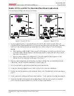
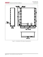
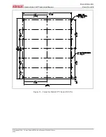
The compact models are designed to be installed in flush mount openings measuring 7.75 H ×5.75 W
inches utilizing a six-hole mounting pattern. The mounting and wiring instructions are as follows:
R
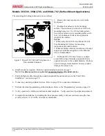
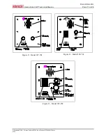
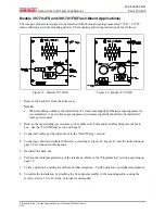
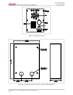
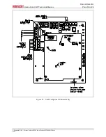
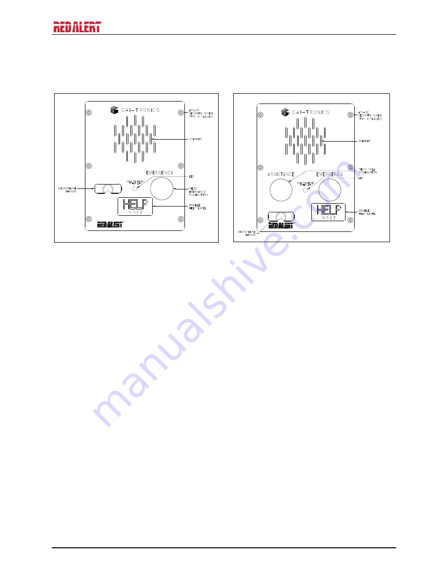
Figure 17. Model 397-700FS
R
Figure 18. Model 397-701FS
1.
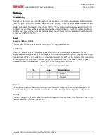
Remove the back box from the front cover.
N
OTES
:
When mounting outdoors, the installation of a (customer-supplied) Ethernet surge suppressor is
recommended. A power line surge suppressor (customer supplied) should also be installed if
local power is used.
2.
Remove the tapered plug(s) as necessary from cable entry holes and feed all cabling into the back
box. See the “Field Wiring” section on Page 18.
3.
Connect all cables per the instructions in the “Field Wiring” section.
4.
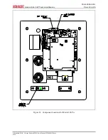
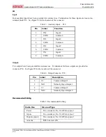
Connect any desired peripheral I/O devices, referring to Figure 22, Figure 23, and the instructions on
page 20 for connection information.
5.
Re-install the back box.
6.
Perform the initial programming of the telephone. Refer to the “Programming” section beginning on
page 23.
7.
Verify operation by calling to and from another telephone. Verify operation of peripheral equipment.
8.
Complete the installation by attaching the front panel assembly to the mounting surface using the
security screws, 10 to 12 in-lbs. of torque recommended.

