background image

P

P

G

G

-

-

6

6

0

0

0

0

0

0


T

T

h

h

r

r

e

e

a

a

d

d


D

D

i

i

a

a

m

m

e

e

t

t

e

e

r

r


G

G

a

a

g

g

e

e


O

O

p

p

e

e

r

r

a

a

t

t

i

i

o

o

n

n


M

M

a

a

n

n

u

u

a

a

l

l


11 


Setting Up the PG-6000 Gage   (continued)


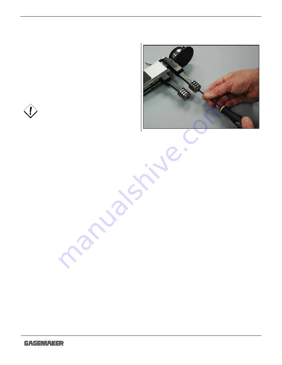
12. Place the washer and lock screw on each roll 

pin. 

 
13. Using the 1/8” hex wrench, tighten the lock 

screw. Eliminate any side to side movement of 
the thread roll, but make sure that the thread 
roll still rotates. 


DO NOT over tighten the lock screw. This 
will prevent the gage from operating 
properly. 


Summary of Contents for PG-6000

Page 1: ...P PG G 6 60 00 00 0 T Th hr re ea ad d D Di ia am me et te er r M Me ea as su ur re em me en nt t G Ga ag ge e OPERATION MANUAL ...

Page 2: ...P PG G 6 60 00 00 0 T Th hr re ea ad d D Di ia am me et te er r G Ga ag ge e O Op pe er ra at ti io on n M Ma an nu ua al l 2 2009 Gagemaker LP OMPG 600010 00 ...

Page 3: ...duction Technical Support 7 Product Information and Updates 7 System Components Component List 8 Setup Procedures Setting Up the PG 6000 Gage 9 Zeroing the PG 6000 Gage Using Gage Blocks 12 Zeroing the PG 6000 Gage Using the MIC TRAC 15 Operating Procedures Inspecting Parts 19 Care and Maintenance Maintenance Tips 22 Warranty Information 22 ...

Page 4: ...P PG G 6 60 00 00 0 T Th hr re ea ad d D Di ia am me et te er r G Ga ag ge e O Op pe er ra at ti io on n M Ma an nu ua al l 4 ...

Page 5: ...o ensure the high performance and operation of our product we urge you to use the included reference materials They contain important information for proper installation setup and use of the equipment Also we recommend that you follow the care and maintenance tips in this manual to keep the equipment working in top condition If your questions have not been addressed in our reference materials cont...

Page 6: ...P PG G 6 60 00 00 0 T Th hr re ea ad d D Di ia am me et te er r G Ga ag ge e O Op pe er ra at ti io on n M Ma an nu ua al l 6 ...

Page 7: ...thread form and pitch The thread roll design allows them to make rolling contact with the threaded part causing minimal wear on thread rolls and eliminating damage to parts Before inspecting parts the PG 6000 gages must be preset to a nominal predetermined dimension For determining the gage s setting dimensions gauging tolerances and specific type of thread roll for the application the Thread Disk...

Page 8: ...tant for understanding the operating instructions Component List Item Description Qty Item Description Qty 1 Gage body 1 10 10 32 X button head lock screw 2 2 Retraction lever 1 11 Lower thread roll 1 3 Indicator binder nut 1 12 Lower thread roll pin 1 4 Indicator clamp 1 13 Lower arm 1 5 Indicator 1 14 Upper arm 1 6 Indicator protector 1 15 Lock screw 2 7 Upper thread roll pin 1 16 Socket head ca...

Page 9: ...e PG 6000 gage involves determining the thread roll type for your application and installing them on the gage Entering some minimal thread information into the Thread Disk for Windows program will provide you with the proper type thread rolls gage setting dimensions and the gauging tolerances for your application 1 Start the Thread Disk for Windows program 2 Select the Thread Type and Thread Class...

Page 10: ...he lock screw and washer from each roll pin 10 Clean the thread rolls and the roll pins on the gage to ensure they are free from debris 11 Slide a thread roll on each of the gage s roll pins The face of the thread roll that is marked with lines and the thread roll type should face outward Note Be sure there is no dirt between the thread roll and the roll pin to enable the thread rolls to spin free...

Page 11: ...etting Up the PG 6000 Gage continued 12 Place the washer and lock screw on each roll pin 13 Using the 1 8 hex wrench tighten the lock screw Eliminate any side to side movement of the thread roll but make sure that the thread roll still rotates DO NOT over tighten the lock screw This will prevent the gage from operating properly ...

Page 12: ...the gage setting dimensions previously printed from the Gagemaker screen in the Thread Disk for Windows software 2 Stack the proper size gage block s for the desired setting dimension 3 Loosen the bent bolt to release the adjuster arm Slide the adjuster arm enough to fit the thread rolls between the gage block s 4 Pull the retraction lever on the PG 6000 and place the thread rolls between the gage...

Page 13: ... l 13 Zeroing the PG 6000 Gage Using Gage Blocks continued 6 Slide the lower adjuster arm approximately 050 away from the upper arm to give the gage the proper preload 7 Tighten the bent bolt to secure the adjuster arm in place 8 Pull the retraction lever on the PG 6000 and insert the thread rolls between the gage block s ...

Page 14: ...e gage between the gage block s to verify the zero setting Note Note the position of the small revolution counter on the indicator before removing the gage Place a piece of masking tape on the backside of the indicator and record the dial setting of the small revolution counter to eliminate incorrect indicator readings 12 Pull the retraction lever and remove the PG 6000 from the gage block s 13 Se...

Page 15: ...nvils together 2 If necessary for documentation purposes press the PRINT pad on the CPU to record the starting location of the anvils 3 Press the INT pad on the CPU to change to internal measurement mode 4 Locate the gage setting dimensions previously printed from the Gagemaker screen in the Thread Disk for Windows software 5 Turn the coarse adjust knob on the MT 3000 to display a measurement that...

Page 16: ...RAC continued 10 Loosen the bent bolt on the PG 6000 gage to release the adjuster arm 11 Slide the adjuster arm to position the gage between the flat face anvils until the thread rolls contact the flat face anvils 12 Remove the PG 6000 gage from the MT 3000 13 Slide the adjuster arm approximately 050 away from the upper thread roll to give the gage the proper preload ...

Page 17: ...TRAC continued 14 Tighten the bent bolt on the PG 6000 gage to secure the adjuster arm 15 Pull the retraction lever on the PG 6000 gage and place the thread rolls between the flat face anvils on the MT 3000 16 While maintaining pressure between the lower thread roll and flat face anvil sweep the upper thread roll side to side to locate the smallest indicator reading ...

Page 18: ...ge on the flat face anvils to verify the zero setting Note Note the position of the small revolution counter on the indicator before removing the gage Place a piece of masking tape on the backside of the indicator and record the dial setting of the small revolution counter to eliminate incorrect indicator readings 20 Pull the retraction lever on the PG 6000 gage and remove it from the MT 3000 21 S...

Page 19: ...ndows software Part Inspection report Inspecting parts using the PG 6000 involves placing the gage on a part in order to compare the nominal functional diameter of the gage to the actual functional diameter of the part 1 After zeroing the PG 6000 gage pull the retraction lever and position the lower thread roll in the threads of the part 2 Using the lower thread roll as a pivot seat the upper thre...

Page 20: ...tor reading on the part Use the gauging tolerances previously printed from the Gagemaker screen in the Thread Disk for Windows software to determine the accuracy of the diameter 5 Hold the gage steady at the largest reading and rock the gage frame left and right to seat both rolls and allow a maximum indicator reading Note Be sure that the small revolution counter on the indicator is pointing to t...

Page 21: ...ter Note A measurement should also be taken adjacent to any thread pullout area to ensure no burrs are causing interference with mating parts 7 Record any deviations on an inspection or calibration report 8 Use the first part you inspected as a control piece to verify repeatability Mark the part at a location where it was inspected and record the deviation from zero 9 During the inspection process...

Page 22: ...its products to be free from defects in material and workmanship for one year from the date of shipment At our option we will repair or replace any defective product upon return prepaid properly packed to our factory in Pasadena Texas This warranty applies to all products when used in a normal industrial environment Any unauthorized tampering misuse or neglect will make this warranty null and void...

Page 23: ...P PG G 6 60 00 00 0 T Th hr re ea ad d D Di ia am me et te er r G Ga ag ge e O Op pe er ra at ti io on n M Ma an nu ua al l 23 NOTES ...

Page 24: ...Gagemaker LP P O Box 87709 Houston Texas 77287 7709 712 East Southmore Ave Pasadena Texas 77502 Phone 713 472 7360 Fax 713 472 7241 Web site www gagemaker com ...

Reviews: