10
REV. 2/23
GB808V POWERUNIT
WARNING
:
Tool must be maintained in a safe working condition at all times and examined on a daily basis for damage or
wear. Any repair should be done by qualified personnel trained on Gage Bilt procedures.
WARNING
:
Excessive contact with hydraulic oil and lubricants should be avoided.
WARNING:
Maintenance personnel
MUST
read and understand all warnings and cautions.
WARNING
:
Disconnect tool from its power source before performing maintenance, cleaning or when replacing worn or
damaged components. Severe personal injury may occur if power source is not disconnected.
WARNING:
Read safety datasheet documents for all applicable materials.
Note:
•
Dispose of hydraulic oil in accordance with manufacture safety datasheet.
•
All tool materials are recyclable except rubber o
’
rings, seals and wipers.
•
SERVICE KIT (808020) should be kept on hand at all times.
This powerunit requires a minimum amount of maintenance. Inspection and correction of minor problems will keep it operating
efficiently and prevent downtime.
At regular intervals, depending upon use, replace all seals in booster. Inspect both hydraulic pistons, and the head cylinder assembly
piston rod for scored surfaces, excessive wear or damage. Replace as necessary
.
* Inspect all hoses and couplings for wear, damage and leaks. Replace/Repair if necessary. (
See hydraulic thread preparation below)
.
* Verify that hydraulic hose fittings and couplings and air connections are secure. Tighten, Replace or Repair if necessary.
(
See hydraulic thread preparation below).
* Cycle the tool several times to assure there are no leaks during use.
* Keep hydraulic system free of dirt. Avoid letting couplers contact a dirty floor.
* Proper care by operators is necessary in maintaining full productivity and reducing downtime.
DAILY MAINTENANCE
* Check oil level in reservoir weekly. Use AW
-
32® or equivalent to maintain correct oil level. Available in quart size Gage Bilt # (A
-
768).
WEEKLY MAINTENANCE
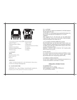
703515 Vacuum Regulator
Tube
(
4) S.H.C.S.
Fitting
Image may not reflect
actual tool
HOW TO CLEAN VACUUM REGULATOR
1.
Remove vacuum regulator (703515) from tube and fitting.
2.
Remove (4) S.H.C.S. from front of regulator and disassemble.
3.
Clean both pieces in clean mineral spirits and blow dry.
4.
Reassemble and connect hoses.
5.
Check vacuum pressure using vacuum gage (703567) (sold separately).
Press gage against the vacuum line or nose assembly to create seal.
Optimum vacuum pressure at nose assembly must be
between 15
-
22 inHg.
(381
-
558.8 mmHg).
Note: The vacuum regulator may visually appear clean, but may still be
contaminated with a thin film. Therefore, the steps above should
be performed to assure best performance.
TROUBLESHOOTING
Providing all maintenance conditions have been met, follow this systematic approach to diagnosis.
1. OIL LEAKAGE.
a.) Hydraulic oil leaks from connections. Tighten threaded connections. Do not use Teflon® tape.
b.) Oil leaks from tool. Determine source of leak and replace worn or defective o'rings and back
-
up rings.
2.
WILL NOT VACUUM PINTAIL.
a.) Check the vacuum line is not kinked and that the bend radius is not too small.
b.) Check vacuum pressure using vacuum gage (703567) (sold separately). Press gage against the vacuum line or nose assembly
to create seal.
Optimum vacuum pressure at nose assembly must be between 15
-
22 inHg.
(381
-
558.8 mmHg).
c.) Clean vacuum regulator. (
See how to clean vacuum regulator).
HYDRAULIC THREAD PREPARATION
IMPORTANT:
Be sure to use thread sealant on all hydraulic fittings, Loctite® 545 or equivalent or a non
-
hardening Teflon® thread
compound such as Slic
-
tite®. Tighten until fitting feels snug and then continue to tighten 1/2 to 1 full turn.
CAUTION:
Over tightening
can easily distort the threads. DO NOT USE TEFLON® TAPE.
CAUTION:
Teflon® tape is an excellent thread sealer, however, if it is not
properly applied, pieces of Teflon® may enter the hydraulic system and cause a malfunction or damage.
Summary of Contents for GB808V
Page 13: ...13 REV 2 23 GB808V POWERUNIT OVERHAUL BOOSTER ASSEMBLY...
Page 16: ...16 REV 2 23 GB808V POWERUNIT GB808V POWER UNIT GB808V POWER UNIT VACUUM BOTTLE ASSEMBLY...
Page 17: ...17 REV 2 23 GB808V POWERUNIT GB808V POWER UNIT FRAME ASSEMBLY...
Page 19: ...19 REV 2 23 GB808V POWERUNIT This page intentionally left blank...