background image

USER MANUAL  


Rev n° 2 28/05/2018


page 8

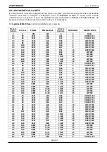
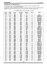
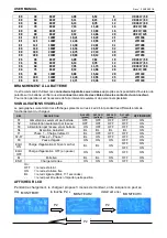
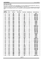
80 

50 

6KW 

5,11 

8,15 

10 

URGS 17/ 63 

80 

60 

6KW 

6,13 

9,78 

12 

URGS 17/ 80 

80 

70 

9KW 

7,15 

11,40 

16 

URZ 17/ 100 

80 

80 

9KW 

8,17 

13,03 

16 

URZ 17/ 100 

80 

90 

9KW 

9,19 

14,66 

20 

URZ 17/ 125 

80 

100 

12KW 

10,21 

16,29 

20 

LTM160 

80 

120 

12KW 

12,26 

19,55 

25 

LTM160 

80 

140 

16KW 

14,30 

22,81 

32 

LMT200 

80 

160 

16KW 

16,34 

26,07 

32 

LMT200 

80 

180 

21KW 

18,75 

27,10 

40 

LMT250 

80 

200 

21KW 

20,83 

30,12 

40 

LMT250 

96 

40 

6KW 

4,90 

7,82 

10 

URGS 17/ 50 

96 

50 

6KW 

6,13 

9,78 

12 

URGS 17/ 63 

96 

60 

9KW 

7,35 

11,73 

16 

URGS 17/ 80 

96 

75 

9KW 

9,19 

14,66 

20 

URZ 17/ 100 

96 

80 

12KW 

9,80 

15,64 

20 

LTM160 

96 

100 

12KW 

12,26 

19,55 

25 

LTM160 

96 

120 

16KW 

14,71 

23,46 

32 

LTM160 

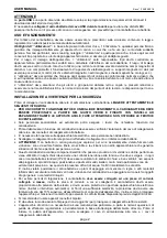
BATTERY CONNECTION 

It is recommended to use relevant 

bi-polar connectors in compliance with Standards

 without the possibility 

of inversion of the polarity on the battery. Also check 

the current connection of the cables in the connector 

contacts

. This operation has to be performed by skilled personnel only. 

VISUAL SIGNALS 

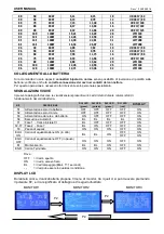
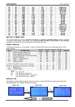
This program illustrates the visual signals on the 4 status LEDs during the various operating statuses of the 
battery charger. 

REF 

DESCRIPTION 

DL4 LED 

(green) 

DL3 LED 

(yellow) 

DL2 LED 

(green) 

DL1 LED 

(red) 

DISPLAY 

S1 

Power supply from battery only 

OFF 

OFF 

OFF 

OFF 

ON 

S2 

Power supply from mains only 

OFF 

OFF 

OFF 

OFF 

ON 

S3 

Power supply from mains and from battery 

ON 

OFF 

OFF 

OFF 

ON


S4 

Autostart execution 

BL 

BL 

BL 

BL 

ON


F1 

Phase 1 – Initial Charge CI


BL 

OFF 

OFF 

OFF 

ON


F2-F7 

Phase 2 – Phase 7 

BL 

ON 

OFF 

OFF 

ON


F8 

Equaliz. standby 

ON 

ON 

ON 

OFF 

ON


EQU ON  Equalisation charge ON (in operation) 

BL 

BL 

ON 

OFF 

ON


OFF 

ON


EQU OFF  Equalisation charge OFF (in standby) 

ON 

ON 

ON 

OFF 

ON


Maintenance 

BL 

BL 

ON 

OFF 

ON


END 

Charging Ended 

ON 

ON 

ON 

OFF 

ON


Where:  
OFF 

= the LED is off 

ON 

= the LED is permanently on 

BL 

= the LED flashes (Blink, T=1seconds) 

- - 

= the LED can be in any condition 

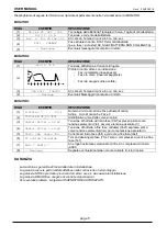
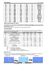
DISPLAY LCD 

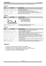
The battery charger offers 3 monitor menus. You can use the P2 button, whose function has been 
illustrated earlier, to navigate between the menus 


P2 

  P2 

MONITOR1 

MONITOR2 

MONITOR3 

P2 

Summary of Contents for SLH 19C

Page 1: ...batterie LIRE ATTENTIVEMENT LES INSTRUCTIONS SUIVANTES Vor dem Anschluss des Batterieladeger ts an die Netzversorgung und dann die Batterie LESEN SIE DIE FOLGENDEN ANWEISUNGEN AUFMERKSAM DURCH Antes...

Page 2: ...olo personale specializzato ed autorizzato potr eseguire i lavori che richiedono l apertura del caricabatteria Prima della messa in funzione del caricabatteria deve essere verificato l isolamento del...

Page 3: ...9KW 7 20 11 49 16 LMT315 24 240 9KW 7 85 12 53 16 LMT315 36 50 3KW 2 40 3 83 6 URGS 17 63 36 60 3KW 2 88 4 59 6 URGS 17 80 36 70 6KW 3 36 5 36 8 URZ 17 100 36 80 6KW 3 84 6 13 8 URZ 17 100 36 100 6KW...

Page 4: ...LAZIONI VISIVE Il presente paragrafo descrive le visualizzazioni presenti sui 4 Led di stato durante i diversi stati di funzionamento del caricabatteria RIF DESCRIZIONE DL4 LED green DL3 LED yellow DL...

Page 5: ...N CICLO 7 Ph 1 Numero di ciclo di carica e fase attuale di carica Ad Es ciclo di carica 5 e Fase 3 2 C1ID 1PB ST_01 0001 Identificativo unico della curva di carica 3 Vbif 1 68V el 40 4V Tensione di ba...

Page 6: ...NOT TO OBSTRUCT THE VENTILATION SLOTS HOLES Only specialised and authorised staff can carry out jobs that require the battery charger to be opened Before operating the battery charger the insulation o...

Page 7: ...4 240 9KW 7 85 12 53 16 LMT315 36 50 3KW 2 40 3 83 6 URGS 17 63 36 60 3KW 2 88 4 59 6 URGS 17 80 36 70 6KW 3 36 5 36 8 URZ 17 100 36 80 6KW 3 84 6 13 8 URZ 17 100 36 100 6KW 4 80 7 66 10 URZ 17 125 36...

Page 8: ...peration has to be performed by skilled personnel only VISUAL SIGNALS This program illustrates the visual signals on the 4 status LEDs during the various operating statuses of the battery charger REF...

Page 9: ...ging phase E g charging cycle 53 and Phase 2 2 C1ID 1PB ST_01 0001 Unique code of the charging curve 3 Vbif 2 39V el 57 4V Battery voltage at the beginning of the phase Vbif first expressed as element...

Page 10: ...EVILLES EXPANSION L AIDE DES TROUS PR VUS CET EFFET FAIRE ATTENTION NE PAS BOUCHER LES SORTIES D A RATION Seul le personnel sp cialis et autoris pourra ex cuter les travaux qui requi rent l ouverture...

Page 11: ...MT200 24 180 6KW 5 89 9 40 12 LMT250 24 200 6KW 6 55 10 44 16 LMT250 24 220 9KW 7 20 11 49 16 LMT315 24 240 9KW 7 85 12 53 16 LMT315 36 50 3KW 2 40 3 83 6 URGS 17 63 36 60 3KW 2 88 4 59 6 URGS 17 80 3...

Page 12: ...ire intervenir seulement du personnel sp cialis SIGNALISATIONS VISUELLES Le paragraphe suivant d crit les affichages pr sents sur les 4 Led d tat pendant les diff rents tats de fonctionnement du charg...

Page 13: ...charge et phase actuel de charge Par ex cycle de charge 5 et Phase 3 2 C1ID 1PB ST_01 0001 Identificatiant unique de la courbe de charge 3 Vbif 2 39V el 57 4V Tension de batterie au d but phase Vbif...

Page 14: ...s Batterieladeger tes darf nur von spezialisierten und autorisierten Personal durchgef hrt werden Vor der Inbetriebnahme des Batterieladeger tes muss die Isolierung des Netzanschlusskabels und der Ans...

Page 15: ...MT315 24 240 9KW 7 85 12 53 16 LMT315 36 50 3KW 2 40 3 83 6 URGS 17 63 36 60 3KW 2 88 4 59 6 URGS 17 80 36 70 6KW 3 36 5 36 8 URZ 17 100 36 80 6KW 3 84 6 13 8 URZ 17 100 36 100 6KW 4 80 7 66 10 URZ 17...

Page 16: ...al durchgef hrt werden SICHTANZEIGEN Dieser Abschnitt beschreibt die Visualisierungen an den 4 Status Led Anzeigen w hrend der verschiedenen Betriebsstadien des Batterieladeger tes BEZ BESCHREIBUNG DL...

Page 17: ...und aktuelle Ladephase Z B Ladezyklus 5 und Phase 3 2 C1ID 1PB ST_01 0001 Alleinige Kennzeichnung der Ladekurve 3 Vbif 2 09V el 50 2V Batteriespannung zu Beginn der Phase Vbif zuvor ausgedr ckt als S...

Page 18: ...o el personal especializado y autorizado podr realizar los trabajos que requieren la apertura del cargador de bater a Antes de la puesta en funcionamiento del cargador de bater as debe verificarse el...

Page 19: ...0 24 200 6KW 6 55 10 44 16 LMT250 24 220 9KW 7 20 11 49 16 LMT315 24 240 9KW 7 85 12 53 16 LMT315 36 50 3KW 2 40 3 83 6 URGS 17 63 36 60 3KW 2 88 4 59 6 URGS 17 80 36 70 6KW 3 36 5 36 8 URZ 17 100 36...

Page 20: ...operaci n 5 SE ALIZACIONES VISIBLES Este p rrafo describe las visualizaciones presentes en los 4 Led de estado durante los diversos estados de funcionamiento del cargador de bater as RIF DESCRIPCI N D...

Page 21: ...1 N mero de ciclo de carga y fase actual de carga Por ejemplo ciclo de carga 5 y fase 3 2 C1ID 1PB ST_01 0001 Identificaci n nica de la curva de carga 3 Vbif 1 68V el 40 4V Tensi n de la bater a al in...

Page 22: ...O UTILIZANDO AS RANHURAS FORNECIDAS TOMAR CUIDADO PARA N O OBSTRUIR AS RANHURAS DE VENTILA O Somente pessoal especializado e autorizado pode efetuar interven es que solicitem a abertura do carregador...

Page 23: ...7 20 11 49 16 LMT315 24 240 9KW 7 85 12 53 16 LMT315 36 50 3KW 2 40 3 83 6 URGS17 63 36 60 3KW 2 88 4 59 6 URGS17 80 36 70 6KW 3 36 5 36 8 URZ17 100 36 80 6KW 3 84 6 13 8 URZ17 100 36 100 6KW 4 80 7...

Page 24: ...A ES VISUAIS O presente par grafo descreve as visualiza es presentes nos 4 Leds de condi o durante as diferentes condi es de funcionamento do carregador de bateria REF DESCRI O DL4 LED verde DL3 LED a...

Page 25: ...N mero do ciclo de carregamento e fase atual de carregamento Por exemplo ciclo de carregamento 5 e Fase 3 2 C1ID 1PB ST_01 0001 Identificador nico da curva de carga 3 Vbif 1 68V el 40 4V Tens o da ba...

Reviews: