1
Governors America Corp. © 2021 Copyright All Rights Reserved
ESD5500-II Fusion Series Speed Control Unit 1-2020-A4 PIB2180
ESD5500-II Fusion Series
Speed Control Unit
2
SPECIFICATIONS
Performance
Isochronous Operation
± 0.25 % or better
Speed Range / Governor
1 - 7.5 KHz Continuous
Speed Drift
with Temperature
±1 % MAX
Idle Adjust CW
60 % of Set Speed
Idle Adjust CCW
Less than 1200 Hz
Droop Range
1 - 5 % regulation
Droop Adj. Max.
(K-L Jumpered)
400 Hz., ±75 Hz per 1.0 A change
Droop Adj. Min.
(K-L Jumpered)
15 Hz., ±75 Hz per 1.0 A change
Speed Trim Range
± 200 Hz
Remote Variable Speed
Range
500 - 7.5 KHz
Terminal Sensitivity
J
L
N
P
100 Hz, ±15 Hz/V @ 5 KΩ Impedance
735 Hz, ±60 Hz/V @ 65 KΩ Impedance
148 Hz., ±10 Hz/V @ 1 MΩ Impedance
10 V DC Supply @ 20 mA MAX
Reverse Power Protection
Yes
Transient Voltage Protection
60 V
reLIaBILITY
Vibration
1 g @ 20-100 Hz
Testing
100 % Functionally Tested
InPUT / oUTPUT
DC Supply
12 - 24 V DC Battery Systems
Transient and Reverse
Voltage Protected
Polarity
Negative Ground (Case Isolated)
Power Consumption
50mA continuous plus actuator current
Speed Signal Range
1.0 - 50.0 V AC
Actuator Current
@ 77°F [25°C]
8 A MAX Continuous
Speed Sensor Signal
1.0 - 120 V RMS
envIronmenTaL
Ambient Temperature
-40° to 85 °C [-40° to 180 °F]
Relative Humidity
up to 95%
All Surface Finishes
Fungus-Proof and Corrosion-Resistant
PHYSIcaL
Dimension
See Section 3, Installation
Weight
1.8 lbf [820 gf]
Mounting
Any position, vertical preferred
comPLIance / STanDarDS
Agency
CE and RoHS Requirements
1
OVERVIEW
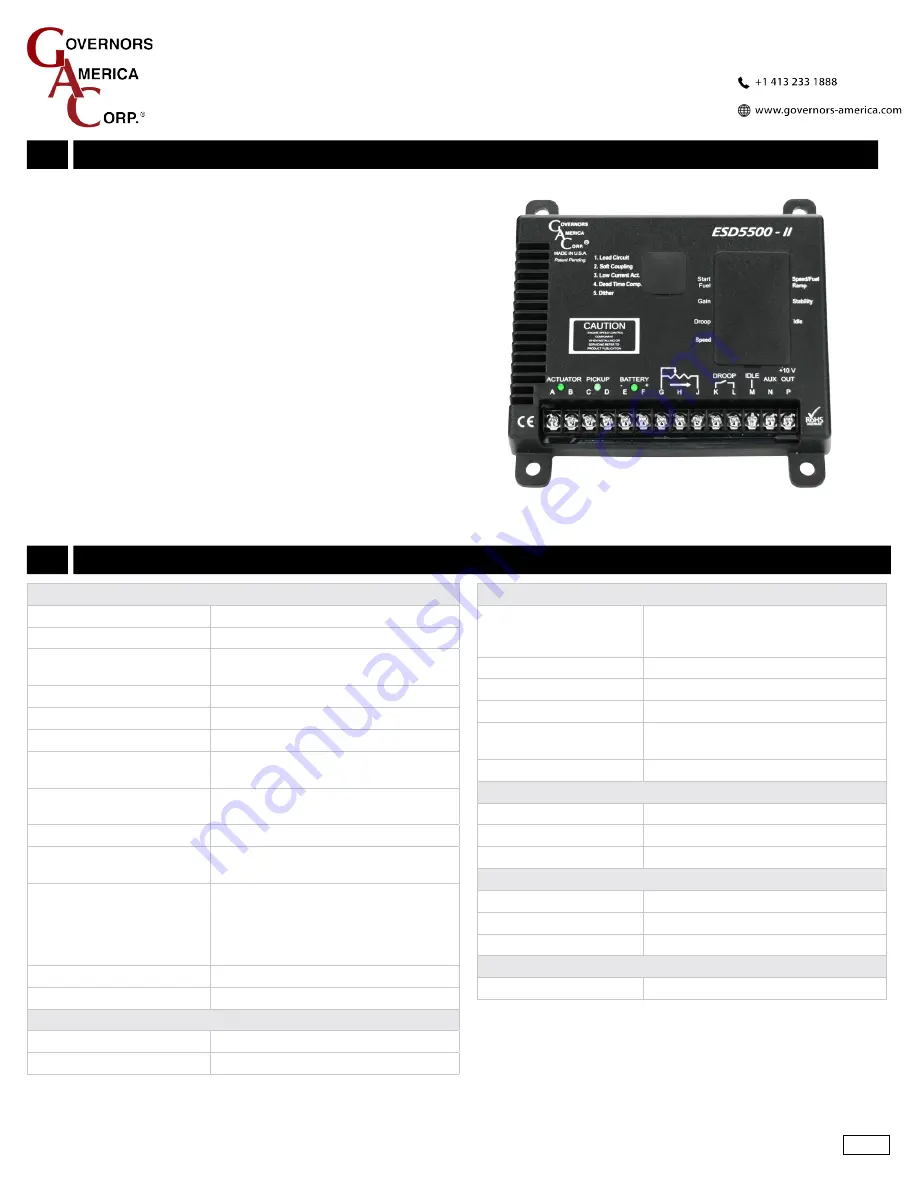
The ESD5500-II speed control unit is designed to precisely control
engine speed with rapid responses to transient load changes. The
ESD5500-II speed control is compatible with all GAC proportional actua-
tors except the ACB2001 electric actuator since this high torque actuator
also requires current limiting available in the ESD5300 Series.
Ruggedly built to withstand all engine environments, the ESD5500-II
has all the same well known features of the ESD5500 and also incorpo-
rates selectable light-force for low current actuators, dither for difficult
engines with respect to stability and integrated anti-windup for both
diesel and gaseous application.
•
Variable Speed Operation
•
Adjustable Droop and Idle
•
Reverse Battery Voltage Protection
•
Selectable light-force and Dither
•
Soft Couple and Lead Circuit Options


