


Section 50
00-02-0271
2018-10-23
-
8 -
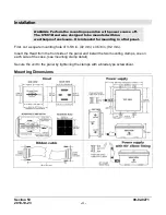
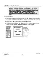
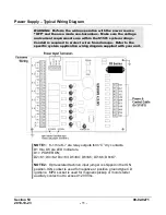
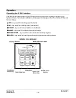
Typical Power Supply Connections
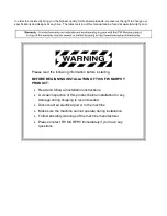
WARNING: Do NOT route the power supply wiring and the sensor
input lead wiring in the same conduit.
a.
Conduit installation
:
1) Remove power before opening power supply cover.
2) Install one 1/2 in. NPT or two 3/4 in. NPT conduits, from customer end of the Power
Supply.
Note:
Follow
NEC
guidelines for maximum number of wires in conduit.
3) Install an approved explosion-proof seal in the conduit within 18 in. (457 mm) of
Power Supply enclosure (seal unused conduit holes).
Important:
Green screw above conduit hole (power supply) is to attach
equipment ground per
NEC
.
b.
Customer Installed Field Wiring:
Install wiring to power supply through conduit
installed in “step 2-a”.
1) Run wiring from the power source to the S1501 power supply.
2) Connect the 120 VAC to the two AC Power Input terminals. Connect equipment
ground to green screw (see schematic below).
3) Connect the 12 or 24 VDC Positive (+) lead to Power Input terminal 12-24 DC.
4) Connect 12 or 24 VDC “DC(–)” lead to the GND terminal. (See “Power Supply
Typical Wiring Diagram”.)
Summary of Contents for Selectronic S1501 series
Page 4: ...THIS PAGE INTENTIONALLY LEFT BLANK...
Page 9: ...Section 50 00 02 0271 2018 10 23 5...
Page 33: ...Section 50 00 02 0271 2018 10 23 29...
Page 34: ......


