background image


Operators and Technicians Manual 


©

 2002 – 2007 FutureLogic, Incorporated. All Rights Reserved. 

MNL  Page 8 of 52  12/07/2007 


MNL-000003  REV.N 

3


Printer Service 

Introduction 

This chapter provides instructions on how to remove the printer to service it outside of 
the game. 

Note:

 While the printer is hot-connectable, it is still a good maintenance procedure to 

turn off the power. 


Important Information!


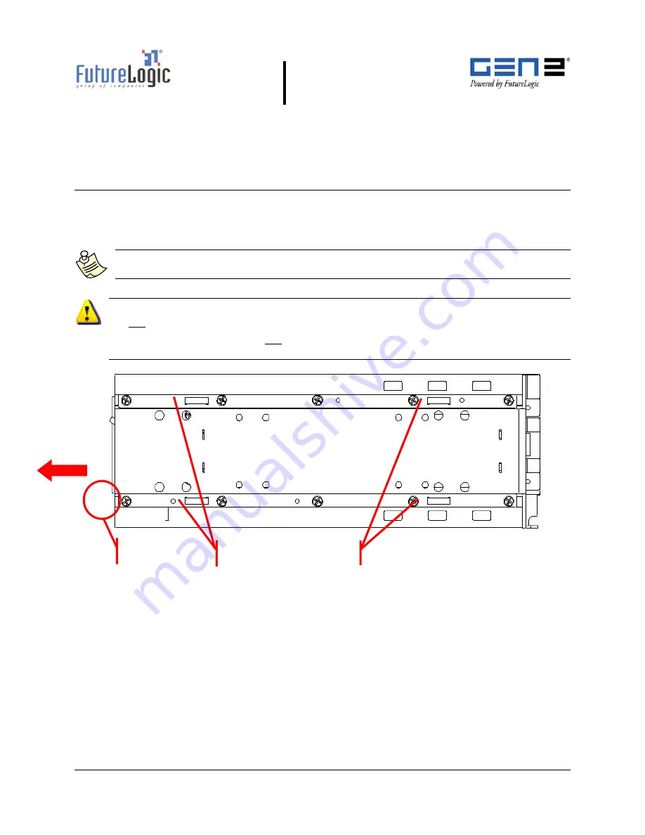
Do not remove the ground screw in the rail as it will release the internal nut! 
After removing the printer, do not slide the unit on a tabletop or other surface. Doing so 
will cause damage to the copper grounding clips on the bottom of the unit.  


Figure 3-1 

Ground Screw and Copper Grounding Clips Location 

Copper Grounding Clips 

Ground Screw 


Ticket 
Output 

Summary of Contents for PSA-66-ST2

Page 1: ...lex While PSA 66 ST2 refers to both the PSA 66 ST2R and PSA 66 ST2N versions of the printer this manual is written primarily for the RS232 interface For additional information on the Netplex interface please contact International Game Technology This document is uncontrolled when printed ...

Page 2: ... mentioned herein are the property of their respective owners This document contains Proprietary and Confidential information and its contents are covered by Non Disclosure Agreement Technical information in this manual is disclosed for informational purposes only No grant of license or use rights of any such information is made by publication or distribution of this manual No part of this guide m...

Page 3: ...nter 9 4 Ports and Dip Switches 11 Introduction 11 Front Bezel Port All Models 11 PSA 66 ST2N GEN2 Netplex Printer 12 GEN2 Netplex Interface Cable 12 GEN2 Netplex Firmware Upload Port 14 GEN2 Netplex Dip Switches 15 PSA 66 ST2R GEN2 RS232 Printer 16 GEN2 RS232 Interface Cable 12 Pin Coiled Cable 16 GEN2 RS232 Interface Cable 14 Pin Coiled Cable 18 GEN2 RS232 Adapter Cable 12 Pin to 14 Pin 19 GEN2 ...

Page 4: ...able Connector 9 Figure 3 3 Slide the Printer until It Locks 9 Figure 3 4 Remove the Paper 10 Figure 3 5 Front Locking Bar 10 Figure 3 6 Push Release Bar 10 Figure 4 1 Front Bezel LED Control Port All Models 11 Figure 4 2 Netplex Interface Cable 12 Figure 4 3 Netplex Firmware Upload Port 14 Figure 4 4 Upload Cable Diagram 14 Figure 4 5 Netplex Dip Switches Top View 15 Figure 4 6 RS232 Interface Ca...

Page 5: ... Pin out 13 Table 4 5 12 Pin Netplex Base Port Pins 13 Table 4 6 Firmware Upload Port Pin out 14 Table 4 7 Netplex 6 Position Dip Switch Settings 15 Table 4 8 Auxiliary COMM Port Pin out 16 Table 4 9 Bezel LED Port Pins 16 Table 4 10 RS232 Power COMM Port Pin out 17 Table 4 11 12 Pin RS232 Base Port Pins 17 Table 4 12 Auxiliary COMM Port Pin out 18 Table 4 13 RS232 Power COMM Port 14 Pin out 18 Ta...

Page 6: ...lease contact International Game Technology Features of the GEN2 printer include The ITH Intelligent Ticket Handling technology which prevents player interference with any part of ticket production or presentation May be mounted on an angle or horizontally Simple paper loading no loose parts Variable paper capacity with different paper trays 300 600 and 900 ticket trays Windows ticket receipt deve...

Page 7: ...perator Indicators and Controls The printer is equipped with status indicators and a FEED button which allow you to manage and interpret the operations of the printer The status indicators are The front bezel light Keypad lights Ready Green Paper Yellow Open Orange Fault Red The following figure illustrates the location of these indicators and controls Figure 2 1 Operator Indicators and Controls S...

Page 8: ...e are six primary sensor functions on the printer These sensors work with the game firmware to provide reliable trouble free operation Any error conditions resulting from these sensors are indicated by the front bezel light and keypad LEDs Table 2 3 describes each of these sensors Table 2 3 Sensors Sensor Description Paper Out The Paper Out sensor is located in the print head It terminates the pri...

Page 9: ...y room temperature this error would most likely be the result of a hardware problem The printer will automatically resume operation after the detected head temperature falls within range Voltage Results if the printer detects a power supply voltage 24VDC to 25VDC outside range This error could be the result of a poor cable connection The printer will automatically resume operation after the power ...

Page 10: ...rinter as indicated by the band around the stack and the label on the bottom of the Paper Tray Tip To prevent a new paper stack from sticking together fan out the paper after you take off the band Figure 2 2 Load a Paper Stack 3 Feed the paper into the Paper Loading Slot and release it once the motor engages and the printer takes hold of the paper The printer automatically pulls through a form or ...

Page 11: ...r obstructions Use the Lid Release Lever located on the top of the unit Do not allow a screwdriver or other probing object to come in contact with the printer This can cause permanent damage to the printer Model PSA 66 ST2 Firmware GRUSA4100 TKT 2 3 COMMUNICATION Interface serial Baud Rate 19200 Data Bits 8 Parity NONE Handshaking XON XOFF HARDWARE PRINT CONTROL Darkness Control 00 Black Bar Index...

Page 12: ...igure 2 6 Open the Lid 3 Remove the jammed ticket If necessary access the paper path through the print mechanism by opening the Mechanism Release Lever Figure 2 7 Clear the Paper Jam 4 Once you clear the jam reverse these steps to return the printer to a ready state 5 Load the paper Cleaning the Print Head To clean the print head use canned air to blow out the paper particles Then use a lint free ...

Page 13: ...ile the printer is hot connectable it is still a good maintenance procedure to turn off the power Important Information Do not remove the ground screw in the rail as it will release the internal nut After removing the printer do not slide the unit on a tabletop or other surface Doing so will cause damage to the copper grounding clips on the bottom of the unit Figure 3 1 Ground Screw and Copper Gro...

Page 14: ...for operations purposes unless it is otherwise protected Discharge your clothing before touching the assembly Discharge tools before use Whenever possible unpack or pack this product only at EOS ESD safe workstations Where a safe workstation is not guaranteed it is important for the user to be electrically discharged before touching the product with his her hands or tools To remove the printer fro...

Page 15: ...ure 3 4 Remove the Paper 5 Push the Front Locking Bar unit to unlock the sliding module from stationary module Slide the drawer module completely out of the stationary module Figure 3 5 Front Locking Bar 6 Push the Release Bar located on the bottom of the unit While holding in the Release Bar gently pull the printer towards you Figure 3 6 Push Release Bar Front Locking Bar ...

Page 16: ...page 16 Note While PSA 66 ST2 refers to both the PSA 66 ST2R and PSA 66 ST2N versions of the printer this manual is written primarily for the RS232 interface For additional information on the Netplex interface please contact International Game Technology Front Bezel Port All Models Figure 4 1 Front Bezel LED Control Port All Models Table 4 1 lists information on the LED bezel port on the GEN2 prin...

Page 17: ...ex Mini Fit Jr 39 01 2125 Mate Molex Mini Fit Jr 39 01 2121 Base Port 1 7 6 12 1 3 2 4 Pin Function 1 GND 2 RX2 3 TX2 4 No Connect 1 2 3 Connector Molex Mini Fit Jr 39 01 4032 Mate Molex Mini Fit Jr 39 01 4030 Connector Molex Mini Fit Jr 39 01 3049 Mate Molex Mini Fit Jr 39 01 3042 Auxiliary COMM Port Pin Function 1 Switched 25VDC 100mA Min 2 NC 3 BGND Bezel LED Control Port Netplex Power COMM Por...

Page 18: ...n as the bezel port pin Table 4 5 12 Pin Netplex Base Port Pins Pin Function 1 BGND 24V Return 2 NETPLEX RXD 3 13VDC 4 SWITCHED 24VDC 5 No Connect 6 MRESET 7 NETPLEX TXD 8 24VDC 9 No Connect 10 RX2 11 TX2 12 AGND I O viewed from the printer Note The Bezel port on the rear of the printer is identical in function and characteristics to the one on the front of the printer Pin Function I O 1 MRESET I ...

Page 19: ...port slide the printer out until the upload port shown in the following figure is visible Then plug an appropriate upgrade cable into the printer This connection may be made while the power is on Figure 4 3 Netplex Firmware Upload Port Table 4 6 Firmware Upload Port Pin out Tip Use the following diagram to make an upload cable Figure 4 4 Upload Cable Diagram DB 9 Female Connect to PC serial port M...

Page 20: ...h a slot on the top of the printer Use the dip switches to select the communications protocol The switches must be set according to Table 4 7 for proper operation Figure 4 5 Netplex Dip Switches Top View Table 4 7 Netplex 6 Position Dip Switch Settings Pos Function Configuration 1 2 3 4 5 6 Reserved Baud Rate Baud Rate Hand Shaking Reserved Reserved OFF ON OFF OFF OFF OFF Note Do not turn reserved...

Page 21: ...it Jr 39 01 2125 Mate Molex Mini Fit Jr 39 01 2121 Base Port 1 7 6 12 Pin Function 1 Switched 25VDC 100mA Min 2 NC 3 BGND 1 3 2 4 Connector Molex Mini Fit Jr 39 01 2121 Mate Molex Mini Fit Jr 39 00 0040 1 2 3 Connector Molex Mini Fit Jr 39 01 4032 Mate Molex Mini Fit Jr 39 01 4030 Connector Molex Mini Fit Jr 39 01 3049 Mate Molex Mini Fit Jr 39 01 3042 Auxiliary COMM Port Bezel LED Control Port RS...

Page 22: ...eration leave the MRESET pin unconnected For MRESET function GND must be supplied to the printer through pin 1 Table 4 11 lists the pin out of the 12 pin base port The Modulated 24VDC pin has the same function as the bezel port pin The function of MRESET is described for the RS232 port above Table 4 11 12 Pin RS232 Base Port Pins Pin Function 1 BGND 24V Return 2 PRINTER TX1 3 No Connect 4 SWITCHED...

Page 23: ... 5 GND 6 24 VDC 7 GND 8 24 VDC 9 Modulated 24VDC 10 GND 11 RS232 RXD 12 RS232 TXD 13 DTR 14 RTS RS232 14 Pin Coiled Cable P N 150 00047 100 Figure 4 7 RS232 Interface Cable 14 Pin Coiled Bezel LED Control Port Auxiliary COMM Port Connector Molex Mini Fit Jr 39 01 3149 Mate Molex Mini Fit Jr 39 01 2140 Connector Molex Mini Fit Jr 39 01 3049 Mate Molex Mini Fit Jr 39 01 3042 Power COMM Port 14 Pin 1...

Page 24: ... 12 07 2007 MNL 000003 REV N GEN2 RS232 Adapter Cable 12 Pin to 14 Pin Figure 4 8 RS232 Adapter Cable Table 4 14 RS232 Adapter Cable Pin outs Pin Function 1 MRSET 2 No connect 3 No connect 4 No connect 5 GND 6 24VDC 7 GND 8 24VDC 9 24VDC 10 GND 11 RX1 12 TX1 13 DTR 14 RTS RS232 Adapter Cable P N 150 00043 ...

Page 25: ...cs to the one on the front of the unit described earlier Table 4 15 Bezel Port Pins Pin Function 1 Modulated 24VDC 2 No connect 3 GND Connector Molex 39 30 1200 Mate Molex 39 01 2120 1 6 7 12 Base Port 1 2 3 Connector Molex 39 01 4032 Mate Molex 39 01 4030 Connector Molex 39 30 0040 Mate Molex 39 01 2040 1 2 3 4 1 5 Connector DB 9 female Mate DB 9 male Cable standard straight pass DB 9 to DB 9 RS2...

Page 26: ...e Port Pins Pin Function I O 1 MRESET I 2 Netplex TXD I 3 12 VDC RS232 optional I 4 Netplex RXD O 5 GND 6 24 VDC 7 GND 8 24 VDC 9 Modulated 24VDC O 10 GND 11 RS232 RXD I 12 RS232 TXD O 13 DTR O 14 RTS O I O viewed from the printer Table 4 18 DB9 RS232 Port Pins Pin Function I O 1 No connect 2 TX O 3 RX I 4 DSR I 5 GND 6 DTR O 7 CTS I 8 RTS O 9 No connect I O viewed from the printer GEN2 RS232 Firm...

Page 27: ...er This connection may be made while the power is on Figure 4 10 RS232 Firmware Upload Port Table 4 19 Firmware Upload Port Pin out Tip Use the following diagram to make an upload cable Figure 4 11 Upload Cable Diagram DB 9 Female Connect to PC serial port Molex Mini Fit Connector Connect to printer upload port 1 2 3 4 RX TX Tie pin 1 to 4 GND 1 3 2 4 Pin Function 1 Port Select 2 RX 3 TX 4 GND Fir...

Page 28: ...hes accessible through a slot on the top of the stationary module The dip switches are used to select the communications protocol The switches must be set according to Table 4 20 Figure 4 12 Dip Switches Top View Table 4 20 RS232 6 Position Dip Switch Settings MODE SW1 JMPR3 SW2 JMPR2 SW3 JMPR1 SW4 JMPR0 9600 ON ON X X 38400 OFF ON X X 57600 OFF ON ON X XON XOFF RTS X X X OFF RTS X X X ON 6 1 ON ...

Page 29: ...in Memory is Reprogrammable via Flash BIOS Self Test Yes Page Mode Full Page Mode Printing Simultaneous 4 Orientation Printing 0 90 180 270 Line and Box Draw Printer Resident Bitmap Graphics Printer Resident Stored in Flash Graphics Paper Loading Automatic Hands Free Paper Feed Manual Method Direct Thermal Top Coated Fanfolded and Perforated Width 66mm Length 156mm Thickness 4 5 mil 1 Color 2 Colo...

Page 30: ...ght and Width Bar codes Interleaved 2 of 5 Code 39 UPC A UPC E UPC E 2 UPC E 5 Codabar EAN 13 EAN 8 Code 128 MSI Memory 1MB with 128k RAM Interface Communications Bi directional RS232C Full Handshaking Set Netplex Environmental Operating temperature 5 C to 65 C Storage temperature 20 C to 75 C Operating humidity 5 to 95 RH Reliability Maintenance No User Maintenance Required Printer Completely Rem...

Page 31: ...n approved papers and complete paper specifications For authorized ticket converters visit our Web site www futurelogic inc com Note Use only approved paper in the printer Use of improper paper may cause damage to the device and will void the printer s warranty Nominal paper thickness 4 5mil Paper dimensions 65mm x 156mm width dimension 1mm Ticket Stack Ticket 300STK 65X156 5M Fanfold Ticket 600ST...

Page 32: ... Description 220 00035 100 GEN2 Printer PSA 66 ST2N Netplex RoHS 220 00037 100 GEN2 Printer PSA 66 ST2R RS232 RoHS RoHS Versions Look for either of these labels Netplex equipped printers meet the Netplex specification of International Game Technology Corporation For additional information please contact IGT Spares P N Description 370 00015 100 Base RoHS 370 00018 100 Bottom Chute RoHS 150 00043 Ca...

Page 33: ...pares P N Description 150 00035 100 Cable Coiled RS232 12 pin RoHS 150 00047 100 Cable Coiled RS232 14 pin RoHS 150 00045 100 Cable Display Adapter RoHS 150 00044 100 Cable Evaluation RS232 12 pin RoHS 150 00013 100 Cable Evaluation RS232 14 pin RoHS 370 00021 100 Floating Part RoHS 370 00024 100 Hinge RoHS 370 00025 100 Hinge Pin RoHS ...

Page 34: ... RoHS 362 00047 101 Label Lid Top PSA 66 ST2N RoHS 362 00047 102 Label Lid Top PSA 66 ST2R RoHS 370 00020 100 Lid Top Purple RoHS 370 00022 100 Locker RoHS 370 00023 100 Locker Base RoHS 370 00016 100 Main Bracket RoHS 140 00030 Mother Board RS232 1 COMM Port 140 00030 Mother Board Netplex 1 COMM Port 140 00030 Mother Board Netplex 2 COMM Ports 140 00030 Mother Board RS232 2 COMM Ports ...

Page 35: ...40 00099 100 Paper Low Sensor Board RoHS 460 00005 100 Platen Shaft Assembly RoHS 350 00031 102 Power Supply RoHS 400 00007 100 Print Mech F03 66 RoHS 310 00112 100 Release Bar Bracket RoHS 310 00115 100 Release Bar Guide RoHS 460 00006 100 Roller Idler RoHS 473 00078 100 Screws 100 pack RoHS 485 00008 100 Spring 50 pack RoHS 370 00026 100 Spring Plate RoHS ...

Page 36: ...erved MNL Page 31 of 52 12 07 2007 MNL 000003 REV N Spares P N Description 482 00012 100 Star Washers 100 pack RoHS 320 00224 101 Ticket Extension Tray 600 Tickets RoHS 320 00224 102 Ticket Extension Tray 900 Tickets RoHS 370 00019 100 Top Presenter RoHS 370 00017 100 Tray Paper RoHS ...

Page 37: ...r M3 holes on the front chassis plate of the GEN2 printer P N Description 130 00024 100 Bezel RoHS 130 00007 Bezel Assembly Ticket Out EZ Pay 130 00008 Bezel Assembly Ticket Out LXS S T EZ Pay 130 00017 100 Bezel Assembly Top Box EZ Pay RoHS 130 00009 100 Bezel BZL SHORT ANGLED_FLG ROHS YEL 130 00021 100 Bezel BZL LONG ANGLED_FLG ROHS YEL 310 00239 Bracket Bezel 19 Upright GK SST 310 00240 Bracket...

Page 38: ... N Description 310 00244 Bracket Bezel GK 17 Upright SST 310 00243 Bracket Bezel GK 17 Upright TI 310 00241 Bracket Bezel S2K TB SST 310 00242 Bracket Bezel S2K TB TI GOLD 310 00238 Bracket Mount EZ Pay TB 17 Upright 140 00096 100 PCBA LED_LONG GEN2 GRN RoHS 140 00096 101 PCBA LED_LONG GEN2 BLU RoHS 140 00044 PCBA Vis Wide Bz Lt EZ Pay ...

Page 39: ...ssed or implied Note The information contained in the following schematics is copyrighted information and is the exclusive intellectual property of FutureLogic Incorporated All rights are reserved No transfer or grant of rights is created by the publication of this information Working on the PCBA When working on the PCBA Install ground lug with two wires from ground cable assembly onto PCBA using ...

Page 40: ...002 2007 FutureLogic Incorporated All Rights Reserved MNL Page 35 of 52 12 07 2007 MNL 000003 REV N This information is copyrighted material and is the exclusive intellectual property of FutureLogic Incorporated All rights are reserved ...

Page 41: ...002 2007 FutureLogic Incorporated All Rights Reserved MNL Page 36 of 52 12 07 2007 MNL 000003 REV N This information is copyrighted material and is the exclusive intellectual property of FutureLogic Incorporated All rights are reserved ...

Page 42: ...002 2007 FutureLogic Incorporated All Rights Reserved MNL Page 37 of 52 12 07 2007 MNL 000003 REV N This information is copyrighted material and is the exclusive intellectual property of FutureLogic Incorporated All rights are reserved ...

Page 43: ...002 2007 FutureLogic Incorporated All Rights Reserved MNL Page 38 of 52 12 07 2007 MNL 000003 REV N This information is copyrighted material and is the exclusive intellectual property of FutureLogic Incorporated All rights are reserved ...

Page 44: ...002 2007 FutureLogic Incorporated All Rights Reserved MNL Page 39 of 52 12 07 2007 MNL 000003 REV N This information is copyrighted material and is the exclusive intellectual property of FutureLogic Incorporated All rights are reserved ...

Page 45: ...002 2007 FutureLogic Incorporated All Rights Reserved MNL Page 40 of 52 12 07 2007 MNL 000003 REV N This information is copyrighted material and is the exclusive intellectual property of FutureLogic Incorporated All rights are reserved ...

Page 46: ...002 2007 FutureLogic Incorporated All Rights Reserved MNL Page 41 of 52 12 07 2007 MNL 000003 REV N This information is copyrighted material and is the exclusive intellectual property of FutureLogic Incorporated All rights are reserved ...

Page 47: ...002 2007 FutureLogic Incorporated All Rights Reserved MNL Page 42 of 52 12 07 2007 MNL 000003 REV N This information is copyrighted material and is the exclusive intellectual property of FutureLogic Incorporated All rights are reserved ...

Page 48: ...002 2007 FutureLogic Incorporated All Rights Reserved MNL Page 43 of 52 12 07 2007 MNL 000003 REV N This information is copyrighted material and is the exclusive intellectual property of FutureLogic Incorporated All rights are reserved ...

Page 49: ...aining the following software Download Utility Netplex Exit Tester RS232 Exit Tester CommWrangler Download support tool Netplex test kit For testing Netplex printers Hand tools Power driver P1 P2 extended tips 9 32 nut driver Needle nose pliers Pocket screwdrivers standard and Phillips Phillips should be a small diameter shaft Diagonal cutters 1 power strip Thermal ticket stock Complete stock of r...

Page 50: ...F FEED button 2 5 6 Firmware Upload Port GEN2 Netplex 14 GEN2 RS232 22 Front Locking Bar 10 G GEN2 specifications 24 H Head Up error 3 4 I indicators 2 K keypad status lights 3 L LEDs 3 lid release lever 2 M mechanism release lever 7 Missing Black Index Mark error 3 4 N Netplex bezel LED control port 11 dip switches GEN2 15 firmware upload port GEN2 14 interface cable GEN2 12 P paper capacity 1 fe...

Page 51: ...l LED control port 11 dip switches GEN2 23 firmware upload port GEN2 22 GEN2 adaptor cable 19 GEN2 interface cable 12 Pin 16 GEN2 interface cable 14 Pin 18 S schematics 34 self test 6 sensors 3 Drawer Open 4 Paper Low 3 Paper Out 3 Paper Taken 3 Platen Engaged 4 Printer Open 4 spares part numbers 27 status indicators 2 LEDs 3 T TCL Editor 1 Temperature error 3 4 test ticket 6 ticket dimensional sp...

Page 52: ...FutureLogic Inc 425 East Colorado Street Suite 100 Glendale CA 91205 USA Phone 818 244 4700 Fax 818 244 4764 www futurelogic inc com info futurelogic inc com ...

Reviews: