


The PBu is called the
and the period of oscillation Tu is
called the
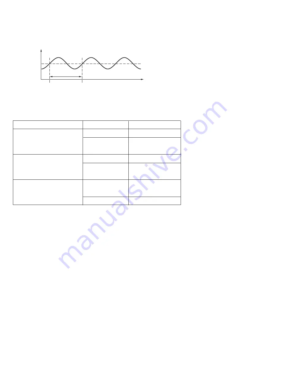
in the flow chart of Figure 3.5 . When this occurs,
the process is called in a
. Figure 3.6 shows a critical
steady state occasion.
Ultimate P Band
Ultimate Period
critical steady state
The PBu is called the
and the period of oscillation Tu is
called the
in the flow chart of Figure 3.5 . When this occurs,
the process is called in a
. Figure 3.6 shows a critical
steady state occasion.
Ultimate P Band
Ultimate Period
critical steady state
Set point
Set point
Tu
PV
Time
If PB=PBu
the process sustains to oscillate
If PB=PBu
the process sustains to oscillate
Figure 3.6 Critical Steady
State
Figure 3.6 Critical Steady
State
If the control performance by using above tuning is still unsatisfactory, the
following rules can be applied for further adjustment of PID values :
If the control performance by using above tuning is still unsatisfactory, the
following rules can be applied for further adjustment of PID values :
ADJUSTMENT SEQUENCE
ADJUSTMENT SEQUENCE
SYMPTOM
SOLUTION
(1) Proportional Band ( P )
PB1 and/or PB2
(1) Proportional Band ( P )
PB1 and/or PB2
(2) Integral Time ( I )
TI1 and/or TI2
(2) Integral Time ( I )
TI1 and/or TI2
(3) Derivative Time ( D )
TD1 and/or TD2
(3) Derivative Time ( D )
TD1 and/or TD2
Slow Response
Slow Response
High overshoot or
Oscillations
High overshoot or
Oscillations
Slow Response
Slow Response
Slow Response or
Oscillations
Slow Response or
Oscillations
Instability or
Oscillations
Instability or
Oscillations
High Overshoot
High Overshoot
Decrease PB1 or PB2
Decrease PB1 or PB2
Increase PB1 or PB2
Increase PB1 or PB2
Decrease TI1 or TI2
Decrease TI1 or TI2
Increase TI1 or TI2
Increase TI1 or TI2
Decrease TD1 or TD2
Decrease TD1 or TD2
Increase TD1 or TD2
Increase TD1 or TD2
Table 3.2 PID Adjustment Guide
Table 3.2 PID Adjustment Guide
33
UM9300 2.0
UM9300 2.0
CPB Programming : The cooling proportional band is measured by % of PB with range 1~255. Initially set 100%
for CPB and examine the cooling effect. If cooling action should be enhanced then
, if cooling
action is too strong then
. The value of CPB is related to PB and its value remains unchanged
throughout the self-tuning and auto-tuning procedures.
decrease CPB
increase CPB
Adjustment of CPB is related to the cooling media used. For air is used as cooling media, adjust CPB at 100(%).
For oil is used as cooling media, adjust CPB at 125(%). For water is used as cooling media, adjust CPB at
DB Programming: Adjustment of DB is dependent on the system requirements. If more positive value of DB
( greater dead band ) is used, an unwanted cooling action can be avoided but an excessive overshoot over
the set point will occur. If more negative value of DB ( greater overlap ) is used, an excessive overshoot over the
set point can be minimized but an unwanted cooling action will occur. It is adjustable in the range -36.0% to
36.0 % of Pb1
( or PB2 if PB2 is selected ). A negative DB value shows an overlap area over which both outputs are active. A
positive DB value shows a dead band area over which neither output is active.
DB Programming:


