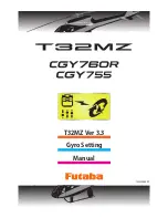
background image

11

Swash Basic

Swash Basic

H-1

Swash Type

ELE

PIT

AIL

H3-120

ELE

PIT

AIL

H3-140

ELE

PIT

AIL

H3-90

ELE2

ELE

PIT

AIL

H4-00

ELE2

FRONT

ELE

PIT

AIL

H4-45

ELE

PIT

AIL

H-1

(4) SWASH Type: Swash change to plate type    

Select the swash plate type.  When you change the setting, other data is 
initialized.

Setting: H-1 / H3-120 / H3-140 / H3-90 / H4-00 / H4-45


Initial setting: H3-120

WARNING 

 All of the swash plate parameters are reset when the swash plate 

type is changed.  Doing so eliminates any possible errors or mal-
functions within the system. After changing the swash plate type, 
Please proceed through the entire setup process once again before 
attempting to fly the model.

AIL --------------------Aileron  servo
ELE ----------------- Elevator  servo
PIT ---------Collective pitch servo
ELE2 ---- Second elevator servo

Your transmitter should be reset to the default settings and the swash plate 
type selected with the transmitter should be set to "H-1" or single servo 
mode.  All CCPM mixing is set up and handled in the CGY, and the transmit-
ter functions should not be used.  Before starting model set-up, be sure that 
all dual rates, pitch curve, and endpoint values are set to 100/100. 

(5) Servo Dir #: Servo direction #   

Using different servo combinations will create the proper swash plate servo 
movement in electronic CCPM models (eCCPM).  In the H3-xx swash 
mode, three of the swash servos directions are changed by pressing the 
Servo Dir #.  Choose the combination number which produces level swash 
plate travel with a collective pitch input from the transmitter.  There are 8 
combination choices for the H3-xx swash mode.  On H4-xx swash mode, 
there are 16 combination choices.  After selecting the combination number, 
aileron, elevator, pitch, and 2nd elevator servo parameters are automati-
cally set.

Note:

 Occasionally the aileron or elevator function directions are reversed 

even though collective pitch direction is correct.  In this case, use the "SWS.
Dir parameter on the following screen (4/6) to fix this later.

Summary of Contents for CG3V76OR

Page 1: ...Gyro Setting T32MZ Ver 3 3 Manual 1M23Z06809 ...

Page 2: ...c Governor Basic Setting 19 Expert Menu Map 21 RUD Expert Rudder Gyro Expert Setting 22 FLT Expert Aileron Elevator Gyro Expert Setting 25 Swash Detail Swash Detail Setting 26 GOV Expert Governor Expert Setting 29 The descriptions and screens in this manual are subject to change with version upgrades With this update the T32MZ has the same functions as the GPB 1 The CGY755 CGY760R can be set up fr...

Page 3: ...M L Lmt H rpm Low limit idling RPM FLT EXPERT HeadHld A Head hold aileron StopTune A Stop tune aileron HeadResp Head Response HeadHld E Head hold elevator StopTune E Stop tune elevator RUD EXPERT EXP AVCS Rudder exponential AVCS EXP NORM Rudder exponential NORMAL CNT DlIn Control delay in CNT DlOut Control delay out ANG Pirouette speed Tail Resp Tail response A Wired connection Advanced settings a...

Page 4: ...nect the CGY760R CGY755 and T32MZ connection cable with the power off When copying data from Gyro A to Gyro B Connect the gyro A to the T32MZ and press Start Enter the data of A into T32MZ Connect Gyro B to T32MZ and press GY Settings Transfer Put data on A into gyro B Select Start This will download the gyro data to the T32MZ When GY Settings Transfer is selected the gyro setting data saved in T3...

Page 5: ...u need to reconnect the cable and download the data First wired connection Next Wireless tunings 2 Select Start This will download the gyro data to the T32MZ 1 2 SETTING T32MZ S I F P BOX CGY755 CGY760R 1 3 Select Wireless Tuning 3 2 4 Items that can be set wirelessly are displayed 4 1 Select Gyro setting on the last page of Helicopter Model Menu 2 Select Start CGY Connection Cable included with g...

Page 6: ...nu of your transmitter DG1 Assigning DG1 to a switch or flight mode allows the use of two separate values for the condition selectable parameters If you set a condition switch channel using the AFR function on that channel set a flat point curve for each flight condition Then you can utilize all 5 flights conditions Set the point curve with AFR for each flight condition of the transmitter Governor O...

Page 7: ...r screen Basic menu screen Flight Tune Aileron Elevator Swash Basic Swash Rud Basic Rudder Gov Basic Governor S BUS Basic Swash Detail Swash FLT Expert Aileron RUD Expert Rudder GOV Expert Governor Internal Rx RF type Home Screen Home Screen ...

Page 8: ...nu As the name suggests this menu allows changes to the basic settings of CGY Make sure to set each BASIC MENU Basic menu screen Flight Tune Aileron Elevator Swash Basic Swash Rud Basic Rudder Gov Basic Governor S BUS Basic ...

Page 9: ...ase select all swash servo types in SWH basic servo type Setting AN 70Hz DG 760μS DG 285Hz Initial setting DG 285Hz WARNING The servo type parameter within the CGY must match the type of servo you are using Incorrect setting may damage the CGY or the servo Incorrect setting may also result in a loss of control during flight S BUS connection Condition on change channel Using the methodology describe...

Page 10: ...ich are good for not only 3D but also F3C flying F3C Mode and L SCALE Large scale model Mode are for unique or special tuning types only When the style is changed setting of AIL ELE RUD is re initialized and defaults are changed L SCALE Initial parameter mode corresponding to a large machine with a total length of 2 5m or more 2 Gyro Set Dir Mounting direction Set the roll axis pitch axis yaw axis...

Page 11: ... should be set to H 1 or single servo mode All CCPM mixing is set up and handled in the CGY and the transmit ter functions should not be used Before starting model set up be sure that all dual rates pitch curve and endpoint values are set to 100 100 5 Servo Dir Servo direction Using different servo combinations will create the proper swash plate servo movement in electronic CCPM models eCCPM In th...

Page 12: ...pitch axis will compensate when the helicopter rolls pitches Pick the helicopter up and roll the helicopter to the right The CGY should compensate by add ing left cyclic to the swash plate Pick the helicopter up and rotate the nose of the helicopter downward The CGY should compensate by adding aft cyclic to the swash plate If the CGY compensates in the wrong direction then it will be necessary to ...

Page 13: ... parameter saves the zero collective pitch point into the CGY Setting method Touch the Pit Zero rate button to enter the setting mode Sure Is displayed Operate the throttle stick to 0 degree pitch If you touch the Yes button The zero pitch signal will be saved to the CGY 16 Pit Low Pitch low memorizing This parameter saves the full negative collective pitch point into the CGY Setting method Touch ...

Page 14: ... Gyro base gain setting This sets the Cyclic Gyro Base Gain If the Rotor Head Gain Rot HD Gn Channels are set to INH within the CGY SBUS BASIC menu then the remote transmitter gain adjustment is not available Thus the actual work ing gain for the cyclic gyros is set by using the Base Gain button within this parameter Set to 100 a transmitter Gain value of 100 will display 100 on this pa rameter If...

Page 15: ...e will reach the desired CYC Rt slower and accelerate slower to the desired angular rate Note Setting this value too high could lead to a jerky feeling when mak ing rapid stick corrections a value too low will give you the impression the model is not following the pilot s stick inputs Values of between 20 60 are the suggested range for most helicopters Setting ranges 0 100 Initial value Cnt AuthEL...

Page 16: ...ades this function is not needed If you do notice a slight tendency for the nose to try to rise or fall with collective input in creasing ELE Comp will reduce this behavior Setting ranges 0 100 Initial value 0 8 HP Auth High pitch authority When a rotor blades angle of attack is increased the rotor blade becomes less reactive in turn the helicopter might not feel as reactive at high pitch angles I...

Page 17: ...ro Dir Setting value Normal Reverse Initial value Normal 3 Work Mode Gyro working mode The available choices are CMT Normal or AVCS The CMT mode will allow you to select either AVCS or Normal mode via the transmitter In Normal mode the gyro will always operate in Normal Rate Mode and when AVCS is selected it will always operate in AVCS Mode Setting CMT Normal AVCS Initial setting CMT 4 GY Gain Gyr...

Page 18: ...on gear N2 Gear ratio N1 N2 Carry values less than 1 1000 to the next whole number 3 Pole Num Pole number This parameter is used when using a direct phase sensor attachment to a brushless motor lead Input the motor pole count as specified by the brush less motor manufacturer When using any revolution sensor other than a direct phase sensor type set the pole number to 2p Note For nitro use set to 2p...

Page 19: ...ned on and off by a switch When Battery Fail Safe is enabled items for setting the throttle servo posi tion are displayed The setting method is the same as Stick sw so please refer to this section of the manual for information on setting this function 8 BAT F S Battery fail safe When the receiver battery voltage becomes equal to or less than BFS Volt set in the GOV EXPERT menu the battery fail saf...

Page 20: ...SBUS2 rpm out RPM display on transmitter When displaying the rpm with the telemetry function set it to ACT Setting ACT Active INH Inhibit Initial setting INH 15 SBUS2 rpm Slot RPM display on transmitter Set the slot number of the telemetry rotation sensor registered on the transmitter side This must be set so that no slots overlap one another 16 Rev Sensor Revolution sensor testing This menu is ut...

Page 21: ...21 Expert Menu Expert Menu 7KLV PHQX HQDEOHV WKH XVHU WR IXUWKHU UH QH WKH J UR DQG JRYHUQRU VHWWLQJV Expert Menu Swash Detail Swash FLT Expert Aileron Elevator RUD Expert Rudder GOV Expert Governor ...

Page 22: ...l rotor pushrod prior to making adjustments with this parameter Setting ranges 240 0 240 Initial value 0 2 EXP AVCS EXP NORM Rudder exponential This parameter sets the feel of the tail rotor control around center When set to 0 the control curve is linear Using a value the tail rotor will be more sensitive around neutral conversely using a value will soften the feeling around neutral The RUD EXP pa...

Page 23: ...er the setting mode and set the delay amount Do the same for the other side Setting ranges 0 20n Initial value 15n 4 CNT DlOut Control delay out This parameter sets the delay when the stick is returned back to the neu tral position This parameter is useful to tune how aggressively the tail rotor stops following a pirouette The higher the value the softer the stop This parameter must be adjusted in...

Page 24: ...t immediately after to help cure the sudden change in torque but it does not allow the large tail rotor input to alter the axial behavior of the helicopter Setting ranges 0 200 Initial value 0 8 Tail Resp Tail response The goal is to match the response between the helicopter tail response and the gyro control This feature is utilized to do so 1 is the fastest response Gener ally if the tail respon...

Page 25: ...ileron control input increasing StpTune A will reduce this bounce Setting ranges 0 250 Initial value 80 3 StopTune E Stop tune elevator Cyclic stop tuning on the elevator axis If the helicopter after an elevator flip continues to coast lowering StopTune E will create a harder stop action to remove the coasting If the helicopter continues to coast after an elevator flip lowering the Stop tune E will ...

Page 26: ...ameter adjusts the pitch to 2nd elevator mixing rate The rates can both be adjusted individually for both full high and low collective positions Note This setting is only available if the H4 xx swash mode has been selected Setting ranges 30 150 Initial value 100 4 AIL PIT aileron collective pitch mixing rate At the middle collective pitch check that during right to left and left to right aileron a...

Page 27: ... not be used when H4 00 swash mode is selected Setting ranges 30 150 Initial value H3 120 50 except H3 120 100 9 ELE ELE2 elevator 2nd elevator mixing rate This parameter adjusts the elevator to 2nd elevator mixing rate The rate can be adjusted separately for up and down directions individually Note This setting is only available if the H4 xx swash mode has been selected Setting ranges 30 150 Init...

Page 28: ...e on eleva tor input Having previously set the ELE PIT and ELE AIL parameters if during rapid movement of the elevator axis the swash plate is not staying level use the Speed Comp button to match all servo speeds Note a will slow the Aileron Pitch Servo will reduce speed comp on Aileron Pitch Servo Setting ranges 0 100 Initial value H3 120 50 except H3 120 0 15 SWASH Rot Swash rotation Using the S...

Page 29: ...setting on the transmitter Fixed This is the suggested mode for use with electric motors This setting ensures that there is a fixed throttle input as is related to the helicopter revolution Tx Curve If this mode is selected the CGY uses the exact throttle input from the transmit ter As such the throttle curve setting on the transmitter is required Note when the Rev Lmt mode is selected this mode sh...

Page 30: ...is to become active The default value is 60 In this case the governor will not engage until the engine rpm reaches 60 of the set rpm If you feel that the time for governor engagement is too slow decrease the value to 50 55 The starting time will be faster Setting ranges 50 90 Initial value 60 10 BFS Volt Battery F S voltage setting This parameter sets the battery fail safe and low battery alarm vo...

Page 31: ...5 7 21 oak kandakajicho 8F 3 4 Kandakajicho Chiyoda ku Tokyo 101 0045 Japan 7 87 25325 7 21 Refer to the manual provided with the product for the installation method and precautions of the transmitter and gyro ...

Reviews: