background image

7.  FISH FINDER OPERATIONS

7-3

7.3

How to Activate the Fish Finder

Select a fish finder display at the home screen. See section 1.8.

7.4

How to Start, Stop Transmission

Transmission can be controlled from the RotoKey menu. Long-push the 

RotoKey


and select [Transmission] to start and stop transmission alternately.

7.5

How to Select a Display

Your fish finder has these display modes: single frequency (50 kHz or 200 kHz), dual 
frequency (50 kHz + 200 kHz), bottom lock, bottom zoom, marker zoom, A-scope, and 
bottom discrimination.

7.5.1

How to select a single frequency or dual frequency
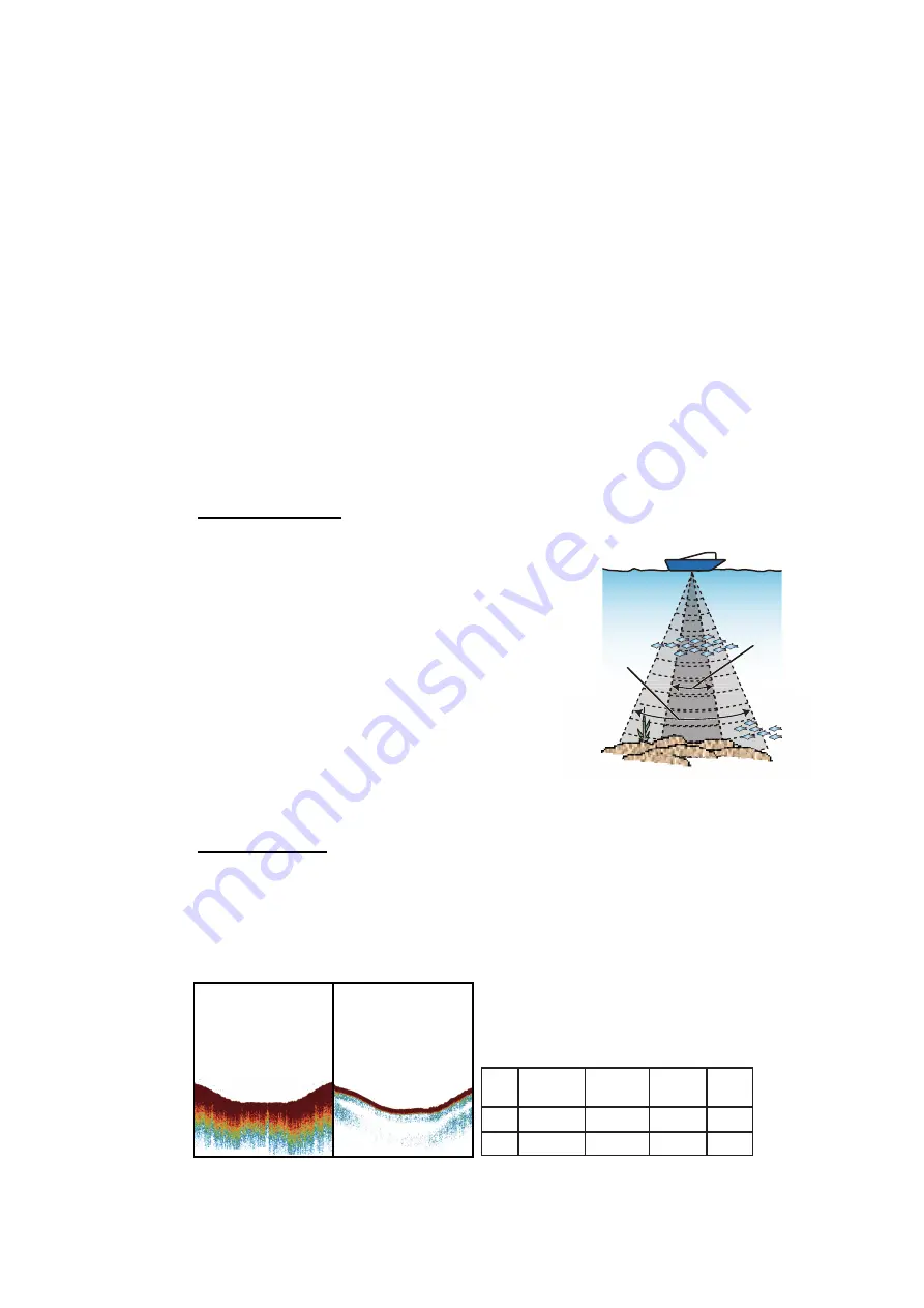
Single frequency

The single frequency display shows either 
the low-frequency or high-frequency picture 
on the full screen. Select a frequency ac-
cording to your purpose.

•  A low frequency gives a wide detection ar-

ea. Use the low frequency for general 
search and to find bottom conditions.

•  A high frequency gives better resolution. 

Use the high frequency to inspect a school 
of fish.

To select a single frequency display

, open 

the RotoKey menu, select [Frequency] then [200 kHz] or [50 kHz]. 

Dual frequency

The dual frequency display provides both low- and high-frequency pictures. Use the 
dual frequency display to compare the same picture with two different sounding fre-
quencies. The low-frequency picture is on the left, and the high-frequency is on the 
right.

To select a dual frequency display,

 open the RotoKey menu then select [Frequen-

cy] and [Dual]. 

High 
frequency

Low 

frequency

Low

frequency

High

frequency

Freq. 
(kHz)

Low

High

Beamwidth Resolution

Detection 
range

Bottom 
tail

Wide

Narrow

Low

High

Deep

Shallow

Long

Short

Summary of Contents for GP-1870F

Page 1: ......

Page 2: ...elemental chlorine free FURUNO Authorized Distributor Dealer 9 52 Ashihara cho Nishinomiya 662 8580 JAPAN A JUN 2012 Printed in Japan All rights reserved F FEB 02 2015 Pub No OME 44770 F GREG GP 1670...

Page 3: ...are no international standards for the battery recycle symbol The number of symbols can increase when the other countries make their own recycle symbols in the future This manual has been authored wit...

Page 4: ...cer cable is not connected cover the transducer connector with the supplied cap to prevent electrical shock Mandatory Action Prohibitive Action WARNING CAUTION Warning Caution The operator must read t...

Page 5: ...presented by this equipment is intended as a source of navigation information The prudent navigator never relies exclusively on any one source of navigation information for safety of vessel and crew...

Page 6: ...1 19 1 12 Menu Operation 1 20 1 13 Object Information 1 21 1 13 1 Simple information 1 21 1 13 2 Detailed information 1 21 1 14 Context Sensitive Menus 1 22 1 15 Man Overboard MOB 1 25 1 15 1 How to...

Page 7: ...ow to Extend a Route on the Screen 4 6 4 4 How to Insert a Point on a Route on the Screen 4 7 4 5 How to Move a Point in a Route on the Screen 4 7 4 6 How to Delete a Point From a Route on the Screen...

Page 8: ...ic fish finder works 7 8 7 6 2 How to select an automatic fish finder mode 7 8 7 6 3 How to adjust the gain in the auto mode 7 8 7 7 Manual Fish Finder Operation 7 9 7 7 1 How to select a display rang...

Page 9: ...al memory or SD card 9 4 9 8 2 How to save screenshots in the internal memory to an SD card 9 4 9 8 3 How to delete screenshots 9 5 10 OTHER FUNCTIONS 10 1 10 1 AIS Operations 10 1 10 1 1 AIS target s...

Page 10: ...13 3 1 How to mount a transducer through the hull 13 2 13 3 2 Transom mount transducer 13 5 13 3 3 How to mount a transducer inside the hull 13 6 13 3 4 Triducer 13 8 13 4 Installation of Sensors opt...

Page 11: ...on The fish finder presents vivid underwater images on a high quality LCD The compact display unit and antenna unit permit installation where space is limited The main features are General Bright 5 7...

Page 12: ...an AIS transponder provides navigational information from AIS transponder equipped vessels within 50 nm Instrument displays steering engine weather and wind with connection of relevant sensors DSC Di...

Page 13: ...PWD 525STID MSD 525STID PWD Transducer Matching Box MB 1100 For connection to 1 kW transducer 50B 6 50B 6B 200B 5S 50 200 1T 50 200 12M 12 24 VDC 100 110 220 230 VAC 1 50 60 Hz Rectifier PR 62 Water t...

Page 14: ...Unit GPA 017S Mast Mtg Kit CP20 01111 004 365 780 Antenna Cable Set CP20 01700 30M 004 372 110 Antenna Cable Set CP20 01710 50M 004 372 120 Transducer 520 5PSD 000 015 204 Thru hull mount plastic 520...

Page 15: ...1 m Cable Assy M12 05BFFM 020 001 105 790 10 w connectors light 2 m Cable Assy M12 05BFFM 060 001 105 800 10 w connectors light 6 m Cable Assy CB 05PM 05BF 010 000 167 968 10 w connectors heavy 1 m C...

Page 16: ...le termina tion resistor Inline Terminator FRU 0505 FF IS 001 077 830 10 Cable Assy 02S4147 1 000 141 082 For speed temp sensor Inner Hull Kit 22S0191 000 082 598 w installation instructions not usabl...

Page 17: ...KeyTM Menus where you select options Context sensitive menus where you select options Lists where you can edit items When you operate a key a single beep sounds to tell you correct operation If you do...

Page 18: ...red on the card If water is at the bottom of the cover DO NOT open the cover Remove the water with a dry cloth completely and then open the cover RotoKeyTM Short push Display the base RotoKey soft con...

Page 19: ...per High Speed SD SDP 2G Y Kingston Kingston SD SD 2GBFE Y Kingston SDHC CLASS 4 SD4 16GB Y Kingston SDHC CLASS 4 SD4 32GB Y Panasonic Panasonic PRO HIGH SPEED SD RP SDK02GJ1A Y Panasonic HIGH SPEED S...

Page 20: ...HC CLASS 4 SDSDRH 8192 903 Y SanDisk Ultra II SD SDSDH 2048 903 Y SanDisk Ultra II SDHC SDSDRH 4096 903 Y SanDisk Extreme III SDHC SDSDRX3 4096 903 Y SanDisk Extreme SDHC SDSDX3 016G J31A Y SanDisk Ex...

Page 21: ...cted soft control is long er than other soft controls its color is light blue and the soft control name is in white characters The soft controls automatically disappear from the screen if not operated...

Page 22: ...lay brilliance as follows 1 Press the key to show the Backlight Brill adjustment window 2 Press the same key again to adjust the brilliance cyclically The window shows the current level with analog an...

Page 23: ...grow larger or smaller where text keeps it s same size and orientation Vector charts lack most topographical features Position fix state indications GPS 2D 2D position fix GPS 3D 3D position fix GPSW...

Page 24: ...lay raster A raster chart is a direct copy or scan of an existing paper chart Raster charts look identical to paper charts All information contained within the chart is printed directly on it What you...

Page 25: ...n the direction indicated on the pressed arrow How to find cursor position range and bearing to cursor position Press any of the four arrows on the CursorPad to move the cursor in the direction in dic...

Page 26: ...spective box when the data is not available For echo sounder fed water temperature data the bars indicate the temperature is equal to or less than 15 C 5 F 1 7 1 How to select the data to display in a...

Page 27: ...yTM to select a display The current selection is circumscribed with a red rectangle Press the RotoKeyTM or ENT key to confirm your selection 1 8 2 How to switch the active screen In multi split screen...

Page 28: ...RL key to show the home screen 2 Use the RotoKeyTM to select the screen to customize 3 Long push the RotoKeyTM to show the PAGE CUSTOMIZATION screen 4 Select the division desired then push the RotoKey...

Page 29: ...sen display appears at the location selected and the rectangle cur sor moves to the adjacent screen 6 Select a display for the right half then push the RotoKeyTM For example select the fish finder dis...

Page 30: ...out the display by rotating the RotoKeyTM The vertical line at the center of the screen is your intended course and the name of the waypoint you are steering to is at top of the line Steer your boat...

Page 31: ...SOG meter Graph navigation data x2 The graph depth water temper ature air temperature atmospheric pressure SOG wind speed plots selected data in a five minute period The navi gation data indications...

Page 32: ...er screens Like with the half screens you can select the navigation data to display in a quarter screen Navigation data x1 Navigation data x2 Navigation data x3 Navigation data x4 Steering Wind angle...

Page 33: ...The right figure shows the choices available with Navigation 6 Select desired data Engine indications The following engine indications are available in the quarter screen Engine instance number The en...

Page 34: ...lected mode appears at the top left hand position Description of orientation modes Head up Displays the chart with the current compass heading of your boat at the top of the screen The heading data fr...

Page 35: ...chart in the following conditions Your boat is not in the current area Take a look at another area Enter a point at another location To move the chart press and hold down the CursorPad to move it to a...

Page 36: ...ted with the CursorPad For example select the General menu 3 Rotate the RotoKeyTM to select a menu item then push the key to show the corresponding options window For example select Font Size and the...

Page 37: ...ation for a point track route and chart ob ject 1 13 2 Detailed information Detailed information is available for points routes and chart objects Put the cursor on the item for which you want to find...

Page 38: ...ected MOVE Move the point selected SKIP Skip the point selected ACTIVATE FROM Start navigating from the point selected DETAILED Get detailed information about the point selected START ROUTE CHECK Chec...

Page 39: ...color DELETE Delete the track in the selected color Points List EDIT Edit the point selected DELETE Delete the point selected PLOT Show the point selected on the plotter display MODE Select the visibi...

Page 40: ...s SD CARD LOAD Copy the screenshots in the SD card to the internal memory DELETE Delete the screenshots RENAME Give the file a new name PREVIEW Show the screenshots selected on the screen Access point...

Page 41: ...y STOP appears at the bot tom left corner Press the ENT key to stop navigation The message Stop navigating to MOB Are you sure appears YES is selected press the ENT key 1 15 3 How to erase an MOB mark...

Page 42: ...ne another on the screen information for each station is presented when FULL INFO is selected from the context sensitive menu Select desired station to find tide information The information is mostly...

Page 43: ...stream information are available For simple information put the cursor on a tide stream marker The Object Information box shows the date time and direction and speed of the tide stream For detailed i...

Page 44: ...1 OPERATIONAL OVERVIEW 1 28 This page is intentionally left blank...

Page 45: ...oKey menu Select Track then push the RotoKeyTM to start or stop recording 2 3 How to Select Recording Method Recording In terval To trace your boat s track your boat s position is stored into the memo...

Page 46: ...ey to close the menu 2 6 How to Hide Show Track by Color When the screen becomes cluttered with many different colors of track you may want to show only a certain color to clear up the screen How to s...

Page 47: ...rack Are you sure appears 3 Select YES then press the ENT key 4 Press the ESC MENU key to close the menu How to delete track color with the context sensitive menu Put the cursor on the track color tha...

Page 48: ...en select TRACK See the indication at the bottom left corner of the menu TRACK RECORD TRACK SHOW TRACK BY COLOR ACTIVE TRACK TRACK COLOR BY TEMP DELETE TRACK BY COLOR TRACK RECORDING METHOD DISTANCE T...

Page 49: ...s put on the screen with the point symbol selected as the default point symbol with the youngest empty point number The position of the point symbol and navigation information range bearing etc are sa...

Page 50: ...w that looks something like the one shown below appears 3 By default the Name field shows the youngest empty point number You can change the name using the CursorPad 4 The Position field shows the pos...

Page 51: ...ress the ENT key to show the position input box The position shown in the box is the cursor position Enter position using the CursorPad After you have entered the position the Save button is automatic...

Page 52: ...Drag the cursor to the new location then press the ENT key The icon moves to the selected position Method 2 Manual input of latitude and longitude from the Points List 1 Select the point with the cur...

Page 53: ...e icon of all points HIDE ALL Hide all points The entry ies in the Mode column change according to your selection 3 6 How to Search Sort Points on the Points List 3 6 1 How to search points 1 Open the...

Page 54: ...t is correctly selected if the point box appears 2 Select DELETE then press the ENT key The message Delete this point Are you sure appears 3 YES is selected push the RotoKeyTM to delete the point 3 8...

Page 55: ...soft control Routes New and menu Routes List 4 2 1 How to create a route from the RotoKey menu 1 Open the RotoKey menu then select Route and New 2 Put the cursor on the first point for the route then...

Page 56: ...the route name if necessary Finally long push the RotoKeyTM The screen something like the one shown below appears 4 Press the ENT key to show the context sensitive menu then do the following to enter...

Page 57: ...n the menu Easy Routing an alyzes each leg for safety in three levels safe leg potentially dangerous leg and un safe leg and color codes them accordingly green for safe yellow for potentially dan gero...

Page 58: ...en a dangerous not nav igable area and your boat This area could be land or a body of water Turn it on to honor this distance 7 Turn off RESPECT DRAUGHT if you want to disregard the depths that are sh...

Page 59: ...the route The Easy Routing created graphic is removed If you saved the route the Start and Destination flags and the route remain on the screen If you exited without saving the route only the Start a...

Page 60: ...ropriate chart card Route calculation has been halted You canceled route calculation Route has not been calculated Route cannot be calculated in a situation other than those men tioned above Reselect...

Page 61: ...the cursor on the point to move then press the ENT key 2 Select MOVE then press the ENT key 3 Drag the cursor to the new location for the point The color of the point icon and the point name turn gray...

Page 62: ...switch between pages with the right and left arrows on the CursorPad Function buttons The three function buttons at the bottom of the Routes List do the functions shown below Use the RotoKeyTM to acce...

Page 63: ...ontext sensitive menu Select EDIT from the context sensitive menu then press the ENT key Rename Rename the route A text input box appears with the current route name in the box Edit the name as approp...

Page 64: ...sensitive menu then press the ENT key The report provides the following information The name of each point The position of each point The bearing to each point The distance to each point The total dis...

Page 65: ...hen press the ENT key 3 Select EDIT from the context sensitive menu then press the ENT key 4 Use the RotoKeyTM to select the Connect button at the bottom of the screen then press the RotoKeyTM to disp...

Page 66: ...cursor on a leg of the route to delete then press the ENT key 2 Select DELETE then press the ENT key You are asked if you are sure to delete the route 3 YES is selected press the ENT key to delete the...

Page 67: ...nects between own ship and the quick point your destination The line shows the shortest path to the destination and the direc tion to go The arrival area the radius of which is set with the ar rival a...

Page 68: ...NT key to show the context sensitive menu 3 Select GOTO then press the ENT key 5 3 How to Select a Route for Navigation There are two methods to select a route for navigation select the route on the s...

Page 69: ...ow the context sensitive menu Select NAVI GATE from the menu See the description and figure in section 5 3 1 for the sequence of events in route navigation Note that the route points of a route create...

Page 70: ...of the rectangular search area around each route leg and route segment The setting range is 0 04 to 0 2 NM DEPTH LIMIT Set the maximum depth to conduct the search for objects shal low water dredged a...

Page 71: ...cts are found the ROUTE CHECK REPORT window shows the ob jects found The figure below shows examples of the route check reports The ROUTE CHECK REPORT is stored in ROUTE CHECK REPORT in the ROUTE CHEC...

Page 72: ...seful when you want to retrace a route from the end to the beginning Put the cursor on a leg in the route then press the ENT key to show the context sen sitive menu Select REVERSE then press the ENT k...

Page 73: ...e size of the place names Select nav aids presentation format Select chart language Predict tide movement Configure the information to show Open the MAP menu and set items according to your operating...

Page 74: ...display The default setting puts the dis play on the left half DISPLAY MODE Select the chart display mode among 2D 2D Perspective and 3D OVERLAY Select the type of overlay to use among Vector Satelli...

Page 75: ...On Off Off Off On Off NAV AIDS LIGHT SEC TORS On No sector No sector Off On Off No sector ATTENTION AREAS On On Off Off On Off TIDES CCURRENTS On Off Off On On Off SEABED TYPE On Off Off Off On Off P...

Page 76: ...chart select the port then press the ENT key The screen closes and the chart appears with the port put at the center of the screen How to hide the place names Do the following to hide the place names...

Page 77: ...LAYS AND SATELLITE OVERLAY 6 5 6 2 2D Perspective Display The 2D perspective display provides an aerial perspective display Select 2D 3D Mode and 2D Perspective from the RotoKey menu to show this disp...

Page 78: ...ent state appears to the right of the orientation mode box The 3D display provides a 3D view of land and sea around your boat Land is shown in different shades of green according to height above the s...

Page 79: ...ttings To es cape from the manual adjustment mode select an orientation mode from the RotoKey menu 6 3 3 How to make the 3D view clearer In the 3D display some topographical features are easier to see...

Page 80: ...and Vector Satellite to show the satellite photo The illustration below shows the vector chart with the satellite photo overlay How to set the level of transparency You can select the level of transpa...

Page 81: ...sea bottom part of the sound wave is reflected toward the source To find the depth to an object the fish finder calculates the time difference between the transmission of a sound wave and the time th...

Page 82: ...you inspect fish The range gain clutter and TVG can be adjusted automatically according to your pur pose cruising or fishing to let you do other tasks The color bar at the left edge of the display sh...

Page 83: ...reen Select a frequency ac cording to your purpose A low frequency gives a wide detection ar ea Use the low frequency for general search and to find bottom conditions A high frequency gives better res...

Page 84: ...y helps you distinguish the fish near the bottom from the bottom echo You can select the bottom lock range with BOTTOM LOCK RANGE in the RANGES menu in the FISH FINDER menu Bottom zoom display The bot...

Page 85: ...and is available in any fish finder mode This display shows the echoes at each transmission with the amplitudes and tone in balance with their intensities This display helps you identify possible fis...

Page 86: ...is indicated graphically Probability display The most probable bottom material is indicated in proportion Characteristics of the bottom discrimination display The bottom discrimination display provid...

Page 87: ...the distance from your boat s draft Be sure to enter your boat s draft How to set the bottom discrimination display Note Auto range is automatically turned on when the bottom discrimination display i...

Page 88: ...modes Cruising and Fishing Cruising tracks the bottom and Fishing searches for schools of fish Cruising uses a higher clutter removal setting than Fishing Do not use Cruising when your purpose is to...

Page 89: ...lly adjusted to always display the bottom echo at the lower of the screen When rotate the RotoKeyTM in the auto mode the message Auto Range mode Can t change Rage appears Manual Change the range with...

Page 90: ...to show the Gain window Turn the key clockwise to increase the gain counterclock wise to decrease the gain 100 is the maximum gain 7 7 4 How to reduce clutter Low intensity spots of noise appear over...

Page 91: ...speed to see the smooth bottom 1 Open the FISH FINDER menu and select PICTURE ADVANCE 2 Select a picture advance speed The options in the window indicate the number of scan lines made per transmissio...

Page 92: ...e full RotoKey menu then select Sensitivity and In terference to show the Interference window Select the level of interference reduc tion to use High provides the greatest degree of interference reduc...

Page 93: ...pears in weaker colors This condition is caused by the attenuation of the ultrasonic wave To display the schools of fish in the same colors use the TVG The TVG auto matically adjusts the gain with de...

Page 94: ...he greater the width White Line ON The contour of the bottom is shown in white 7 15 Alarms There are four types of alarms that produce audio and visual alerts to alert you fish within an area fish len...

Page 95: ...s at Min and Max BOTTOM TYPE ALARM Set the alarm referring to the illustration shown below 7 15 2 How to select the echo signal level that triggers the fish alarm You can specify the echo signal level...

Page 96: ...arks and fish size using a 1 kW transducer the integrated trans ducer 50 200 1T or 50 200 12M is recommended Echo intensity depends on fish species When the fish length differs between the indicated l...

Page 97: ...the style for the fish symbol Off Solid or Striped The size of the symbol is scaled according to fish length 7 16 3 Fish size correction The fish size shown on the display can be different from the t...

Page 98: ...ter temperature indication line moves across the screen from right to left The water temperature scale is available in degrees Celsius or Fahrenheit one of which you can select with TEMPERATURE in the...

Page 99: ...dth determines how much deviation to allow for before shifting the position of the bottom echo For example selecting 5 would shift the bottom echo when its position changes by 5 or more of the Upper L...

Page 100: ...boat In this case select low power and contact the other vessel to request them to re duce their TX power TRANSDUCER Select the transducer used If you use the optional triduc er 525STID MSD or 525STI...

Page 101: ...transducer and the bottom To get the depth from the sea surface to the bottom enter the ship s draft Entry of the ship s draft is required if the bottom discrim ination display is used SPEED CALIBRATI...

Page 102: ...e zero line transmission line shows the position of the transducer The line disappears from the screen when the range is shifted Bottom echoes The strongest echoes are from the bottom and are normally...

Page 103: ...ayers giving a 3D effect Nature of a bottom The nature of a bottom is known from the intensity and length of the bottom tail To find the nature of a bottom use a long pulse length and normal gain For...

Page 104: ...because the ultrasonic wave attenuates as it propagates and the school of fish in deep water tends to be displayed in a weaker color Bottom fish The echoes from the bottom are stronger than the botto...

Page 105: ...of the screen Air bubbles in the water When the sea is rough or the ship makes a quick turn there can be blank spots in the bottom echo see the right illustration These blank spots are caused by air...

Page 106: ...trasonic pulse is transmitted some energy leaves from each side of the beam This energy has the name sidelobe Echoes from sidelobes show on the screen as false images like in the illustration shown be...

Page 107: ...m by pressing the ESC MENU key An alarm icon remains on the screen until the corre sponding alarm is deactivated or the reason for the alarm is gone 8 1 ALARMS Menu The ALARMS menu is where you set th...

Page 108: ...your boat is approaching a destination waypoint The area that defines an arrival zone is that of an imaginary circle which you approach from outside the circle The alarms will be released if your boa...

Page 109: ...emperature There are two types of alarms Within and Outside The With in alarm sounds when the water temperature is within the range set and the Outside alarm sounds when the water temperature is highe...

Page 110: ...larm which requires depth data sounds when the depth is within the alarm range set To set the depth alarm 1 Open the ALARMS menu then select DEPTH ALARM 2 Confirm that the cursor is selecting the top...

Page 111: ...the ALARMS menu then select TRIP ALARM 2 Confirm that the cursor is selecting the top line then push the RotoKeyTM 3 Select On 4 Set the alarm value at Distance 5 Press the ESC MENU key to close the...

Page 112: ...pecified percentage To set the water tank alarm 1 Open the ALARMS menu then select WATER TANK 2 Confirm that the cursor is selecting the top line then push the RotoKeyTM 3 Select On 4 Set the alarm va...

Page 113: ...nsert a blank SD card in the SD card slot Close the cover 2 Open the GENERAL menu and select MEMORY CARD 3 Push the ENT key to give control to the RotoKey functions at the bottom of the screen Rotate...

Page 114: ...ppear Do not remove the card until the message ap pears Press the ESC MENU key to erase the message In the example below the ship s tracks were saved The default file name is FILExxxx xxxx next sequen...

Page 115: ...ush the key 4 You are asked Delete all files from SD card Are you sure The YES button is selected press the ENT key to delete all files When the deleting is completed the message Deleting completed ap...

Page 116: ...orner as INTERNAL or SD CARD 9 8 2 How to save screenshots in the internal memory to an SD card 1 Open the GENERAL menu and select MEMORY CARD 2 Select the Screenshots tab at the top of the screen the...

Page 117: ...not remove the card until the deleting is completed Press the ESC MENU key to erase the message How to delete all screenshots 1 Open the GENERAL menu and select MEMORY CARD 2 Select the Screenshots t...

Page 118: ...9 MEMORY CARD OPERATIONS 9 6 This page is intentionally left blank...

Page 119: ...r is required 10 1 1 AIS target symbols The symbols of AIS targets out of the display range are displayed smaller Position Call sign Name of vessel Speed over the ground Course over the ground CPA Hea...

Page 120: ...m 10 1 4 CPA and TCPA alarms The CPA alarm sounds when an AIS transponder equipped vessel comes within the CPA alarm range set The TCPA alarm alerts you when an AIS transponder equipped vessel is with...

Page 121: ...The LOCATE button when operated displays and centers the AIS SART on the chart and displays the applicable AIS SART icon at the SART s lo cation The CLOSE button closes the dialog window and stays in...

Page 122: ...lect a device for DSC message information Open the INTERFACE menu and select SELECT INPUT DEVICE Select a model name in DSC 10 3 2 DSC message information When a DSC message is received the DSC icon a...

Page 123: ...y TIMER or WATCH Timer operation Select the screen that has the timer then set the timer by operating the down arrow on the CursorPad The setting range is 00 15 to 15 00 Press the ENT key to start or...

Page 124: ...d you want to use them instead of the internal GPS navigator If the external source is a FURUNO make its name appears below Auto Select it to have that device feed respective data DEPTH WATER TEM PERA...

Page 125: ...10 OTHER FUNCTIONS 10 7 10 5 2 Output data Open the INTERFACE menu and select SELECT OUTPUT PGN Select the item to process Select On or Off as appropriate ENVT PARAMETERS Scroll...

Page 126: ...4Bar 40Psi Set engine boost pressure rat ing ENGINE COOLANT PRESSURE 320kPa 2Bar 48Psi 520kPa 4Bar 64Psi 600kPa 6Bar 96Psi Set engine coolant pressure rating FUEL PRESSURE 320kPa 2Bar 48Psi 520kPa 4B...

Page 127: ...ble countries as of January 2014 USA and EU The communication rate and effective range for the wireless LAN can be affected by the electromagnetic waves interfering objects or access point location We...

Page 128: ...al times to close the menu WIRELESS CONNECTION SETUP Security Network Name Signal Status 1 2 2 Encrypted WPE EAP TKPI Open Encryption not supported EAP 4 4 80 dB to 71 dB 70 dB to 61 dB 60 dB to 51 dB...

Page 129: ...eturn to the GENERAL menu 5 Select Plan2Nav LINK 6 Select On If connection to the iOS device is successful iOS Device appears to the right of CONNECTED DEVICE in the Plan2Nav LINK menu 7 Open your iOS...

Page 130: ...t via wireless LAN see section 10 7 then do as shown in the procedure below Only one set of weather data can be stored in the equipment Previous data is written over when new data is downloaded 1 Long...

Page 131: ...ssful appears 10 9 2 How to activate the C Weather data display select the forecast date and time 1 Long push the RotoKeyTM then select C Weather followed by View Data and Display to activate the C We...

Page 132: ...ind direction and speed at a location Put the cursor on a windbarb to show the wind direction and speed at that location Windbarb Speed How to read a windbarb knots km h Calm Calm To read a windbarb s...

Page 133: ...rrow inside the icon moves with wave direction Wave heights of 0 00 m to 7 50 m are shown in colors from light blue to green yellow Wave heights of 7 51 to 15 00 m are shown in colors from yellow or a...

Page 134: ...is play below shows rain to the south and southeast and fog to the northwest You can put the cursor on a weather type icon to see the weather type in alphabet form Note Clear sky and part cloudy icon...

Page 135: ...cursor on a humidity icon to show the humidity at that location Temperature display The temperature display provides surface temperature data with an octagon shaped icon The color of the icon changes...

Page 136: ...10 9 4 C Weather error messages The table below shows the C Weather related error messages Error message Meaning Cannot connect to the selected Access Point Encryption not supported You tried to conn...

Page 137: ...toKeyTM is operated PALETTE Select the color scheme to use SunLight Night or Normal FONT SIZE Set the font size large or small for the main menu context sensitive menu and information windows The font...

Page 138: ...ased on your boat s course when the icon nears the edge of the screen while you scroll the chart QUICK INFO Select what objects to show quick information for On Points Show quick information for point...

Page 139: ...nge even if the vessel is dead in water This change can be reduced by smoothing the raw GPS fixes You can choose the setting from among Off Low Medium and High The higher the setting the more smoothed...

Page 140: ...ION OF THRESHOLD Sets the amount of course in degrees that initiates redrawing of the course in the Auto course up mode COMPASS SETUP Select the type of compass used and set magnetic variation BEARING...

Page 141: ...n environment Low corresponds to pedestrian dynamic platform model For applications with low acceleration and speed High cor responds to at sea dynamic platform model Recommended for applications at s...

Page 142: ...11 CUSTOMIZING YOUR UNIT 11 6 This page is intentionally left blank...

Page 143: ...asten if loosened Ground Check for tight connection and rust Fasten if loosened Remove rust if pres ent Display unit Dust on the cabinet LCD Remove dust from the cabinet with a dry clean cloth Wipe th...

Page 144: ...wer Check for blown fuse Check that the power connector is tightly fastened Check for corrosion on the power cable connector Check for damaged power cable Check the battery voltage is 10 8 to 31 2 V N...

Page 145: ...E REJECTION in the FISH FINDER menu is off The picture sensitivi ty is too low Check the gain setting in manual operation Check if marine life or air bubbles are on the transducer Bottom is too soft t...

Page 146: ...position The bars in the graph at the left show the strength of the RX signal from each sat ellite Satellites that have a signal level of 40 or higher are used to fix position The bars are colored in...

Page 147: ...T User saved items and user settings are not erased SAVE USER DEFAULT Save all current user settings as default user settings Waypoints routes etc stored in the memory are not erased CLEAR MEMORY All...

Page 148: ...40004 Plotter Software version FUR GP 7 X51 CE V2 0 3 57 29 05 2014 SDK version V8 2 68 0R 29 05 2014 BIOS version V2 0 2R 16 11 2011 OS version V3 00 63 00R E43 24 01 2014 FF Program Number 0252397 0...

Page 149: ...ose to the display unit Observe the compass safe distances shown in the Safety Information to prevent disturbance to a magnetic compass Mounting procedure Follow the procedure below to mount the displ...

Page 150: ...ough to pass the connector you may unfasten the connector with a needle nose pliers and 3 8 inch open end wrench Refasten it as shown below after running the cable through the hole If the internal GPS...

Page 151: ...ansducer is always in water regardless of the planing attitude Transducer mounting locations Installation procedure 1 With the boat hauled out of the water mark the location chosen for mounting the tr...

Page 152: ...rly oriented and its working face is parallel to the waterline Note Do not over stress the stuffing tube and locknut through excessive tightening since the wood block will swell when the boat is place...

Page 153: ...5x14 for the transducer with marine sealant for waterproofing Attach the transducer to the mounting location with the self tapping screws 3 Adjust the transducer position so the transducer faces righ...

Page 154: ...le and transducer cable to the display unit Sandpaper 100 Marine sealant Water filled plastic bag Do the installation with the ship moored at a dock etc The water depth should be 6 5 32 feet 2 10 mete...

Page 155: ...paper Also use the sandpaper to roughen the inside of the hull where the transducer is to be mounted 4 Wipe off any sandpaper dust from the face of the transducer 5 Dry the face of the transducer and...

Page 156: ...cer 525STID PWD can be installed by the thru hull method or the inside hull method Pre test for speed and temperature Connect the sensor to the instrument and spin the paddlewheel Check for a speed re...

Page 157: ...Note 3 For single drive boat mount on the star board side at least 75 mm 3 beyond the swing ra dius of the propeller as shown in the right figure Note 4 For twin drive boat mount between the drives H...

Page 158: ...straight edge sight the underside of the sensor relative to the underside of the hull The stern of the sensor should be 1 3 mm 1 16 1 8 below the bow of the sensor or parallel to the bottom of the hu...

Page 159: ...ing the cover downward 2 Insert the sensor s pivot arms into the slots near the top of the bracket 3 Maintain pressure until the pivot arms click into place 4 Rotate the sensor downward until the bott...

Page 160: ...cable where it enters the hull Mark the two mounting holes 6 At each of the marked locations use a 3 mm or 1 8 bit to drill a hole 10 mm 3 8 deep The prevent drilling too deeply wrap masking tape aro...

Page 161: ...the sensor toward boat s bow and tighten the flange 7 Set the sensor section to the sensor casing and tighten the locknut 8 Launch your boat and check for water leakage around the sensor Select a loc...

Page 162: ...rminal Ground the shield to ship s ground Note The fuse is not waterproof Wrap the fuse holder with vinyl tape to keep water out of the fuse holder Black White Shield Display unit back GPS antenna uni...

Page 163: ...0mm Twist shield end Ship on clamp nut gasket and clamp as shown left Fold back shield over clamp and trim Cut aluminum foil at four places 90 from one another Fold back aluminum foil onto shield and...

Page 164: ...ransducer cable to the XDR port Transducer and sensor Use the optional conversion cable 02S4147 to connect the optional speed tempera ture sensor and the transducer to the XDR port ANTENNA UNIT GPA 01...

Page 165: ...etwork and the status of each sensor in the network can be de tected All the CAN bus devices can be incorporated into the NMEA2000 network For detailed information about CAN bus wiring see Furuno CAN...

Page 166: ...powered the INSTALLATION SETTINGS menu appears Enter basic settings following the procedure below 1 If your language is English USA the default language go to step 4 2 LANGUAGE is selected push the Ro...

Page 167: ...your time and UTC time Otherwise go to step 7 1 Rotate the RotoKeyTM to select TIME OFFSET then push the key 2 Press the ENT key Press the up or down arrow on the CursorPad to show a minus sign or si...

Page 168: ...o Select if you have multiple external navigators connected and want to use them instead of the internal GPS In this case the navigator with the low est Node address has priority If you have a FURUNO...

Page 169: ...he RotoKeyTM 9 Repeat steps 7 and 8 for remaining items 10 Press the ESC MENU key several times to close the menu CAN bus NMEA 2000 input output Input PGN PGN Description 059392 ISO Acknowledgement 05...

Page 170: ...ronmental Parameters 130312 Temperature 130313 Humidity 130314 Actual Pressure 130577 Direction Data 130828 Mark Position Information Proprietary PGN 130830 Target Information Proprietary PGN 130831 T...

Page 171: ...en push the ENT key 5 Use the RotoKeyTM to enter the offset Enter a minus value if the value is higher than the actual value or enter a plus value if the value is lower than the actual val ue For exam...

Page 172: ...13 INSTALLATION 13 24 This page is intentionally left blank...

Page 173: ...l 1 Level 2 Level 3 Level 4 Level 5 1 OVERLAY set to Satellite or Chart Shading 2 DISPLAY MODE set to 3D 3 OVERLAY set to Satellite DISPLAY MODE Full Medium Low Tides Custom MARINE SETTINGS NAMES On O...

Page 174: ...ec 10 sec 30 sec 1 min 5 min 10 min 30 min 1 hour PLOTTER FIND PORT SERVICES PORT BY DISTANCE PORT BY NAME TIDE STATIONS WRECKS OBSTRUCTIONS POINTS OF INTEREST COORDINATES Con t from previous page Con...

Page 175: ...XTE ALARM Off On Distance 0 00 to 5 39 0 10NM TEMPERATURE ALARM Off Within Outside Min 004 00 0 00 F to 103 98 Max 004 00 to 103 98 10 00 F SHEAR ALARM Off On Range 00 01 to 19 99 0 10 F DEPTH ALARM...

Page 176: ...phic Probability LEGEND On Off FISH FINDER SETUP DRAFT 20 0 to 39 9 0 0 ft SPEED CALIBRATION 50 to 50 0 TEMPERATURE CALIBRATION 9 90 to 9 90 0 00 F ACOUSTIC SPEED CALIB 50 to 50 0 m s SENSOR SETUP RAN...

Page 177: ...mitted PGNs SELECT INPUT DEVICE SELECT OUTPUT PGN 126992 SYSTEM TIME On Off 127258 MAG VARIATIONS On Off 127259 SPEED On Off 128267 WATER DEPTH On Off 128275 DISTANCE LOG On Off 129025 POSN RAP UP On...

Page 178: ...e Route Restart Stop List Easy Routing Track On Off On Off Data Box 2 Boxes Right 2 Boxes Left 4 Boxes 2D Vector Vector Satellite Raster 2D Perspective 3D Center On Off Mode North Up Course Up Auto Co...

Page 179: ...nshot Auto Mode Fishing Cruising Manual Auto Range Auto Manual Gain 50 kHz 5 5 0 Gain 200 kHz 5 5 0 Frequency 200 kHz 50 kHz Dual Data Box 2 Boxes Right 2 Boxes Left 4 Boxes Standard menu Clutter 0 10...

Page 180: ...RG Bearing C Celsius C TMP Wind Chill Temperature C MAP Registered trademark of the Jeppesen Cor poration CAN BUS Controller Area Network Bus cm centimeter COG Course Over the Ground COOL P Engine Coo...

Page 181: ...iro HUMID Humidity IOR Indian Ocean Region JP Japan kHz kilohertz KM kilometer km h kilometer hour KNT knot kPa Kilo Pascal LAT Latitude Lib Library LOAD Engine Load LON Longitude m meter m s meters s...

Page 182: ...d Through Water SYM Symbol T True T PRS Transmission Oil Pressure T TMP Transmission Temperature TCPA Time to Closest Point of Approach TEMP Temperature TIME Time TRIM Engine Trim TRIP Trip TTG Time T...

Page 183: ...Cursor two types MOB ManOverBoard mark Ship icon four types Ship icon COG line Ship icon Heading line Ship icon track Point single point and route point Wireless LAN RX strength Wireless LAN security...

Page 184: ...ALARM TCPA ALARM ALARM SYMBOL ALARM SYMBOL ARRIVAL ALARM ANCHOR ALARM CROSS TRACK ERROR SPEED ALARM TRIP ALARM TEMPERATURE ALARM SHEAR ALARM DEPTH ALARM FISH ALARM FISH ALARM B L FISH SIZE BOTTOM TYP...

Page 185: ...Type 5 Sheath Type 6 Shielding Type C Steel Y Anticorrosive vinyl sheath SLA SLA DPYCY Diameter Diameter DPYC 1 5 1 5mm2 1 56mm 11 7mm DPYC 2 5 2 5mm2 2 01mm 12 8mm DPYC 4 4 0mm2 2 55mm 13 9mm DPYC 6...

Page 186: ...APPENDIX 3 JIS CABLE GUIDE AP 14 This page is intentionally left blank...

Page 187: ...tallation instructions in this chapter are copied from the manufacturer s AIRMAR Technology Corporation installation guide which is included with your sensor The model numbers mentioned within the doc...

Page 188: ...APPENDIX 4 INSTALLATION OF TEMPERATURE SENSORS AP 16...

Page 189: ...APPENDIX 4 INSTALLATION OF TEMPERATURE SENSORS AP 17...

Page 190: ...APPENDIX 4 INSTALLATION OF TEMPERATURE SENSORS AP 18...

Page 191: ...APPENDIX 4 INSTALLATION OF TEMPERATURE SENSORS AP 19...

Page 192: ...e interval 1 s 2 8 Receiving sensitivity 150 dBm 2 9 SBAS WAAS EGNOS and MSAS 3 PLOTTER FUNCTION 3 1 Effective projection area 0 125 NM to 2 048 NM at equatorial area 3 2 SD card 32 GB max C MAP 4D ch...

Page 193: ...8 126208 464 992 996 127258 128259 267 275 129025 026 029 033 283 284 285 130310 312 830 831 832 5 3 NMEA 0183 Data converter IF NMEA2K2 required Input DPT DSC DSE GGA GLL GNS HDG HDT MDA MTW MWD MWV...

Page 194: ...LC3005AV 000 177 130 10 F FLUSH MOUNT GASKET 1 HGB10AX 000 177 131 10 MJ CABLE ASSEMBLY 1 MJ A3SPF0013A 035C 000 176 666 10 BRACKET FIXING SCREWS 4 VTATM4 8X22 TCC INX 000 177 133 10 DOCUMENT FLUSH MO...

Page 195: ...LC3005AV 000 177 130 10 F FLUSH MOUNT GASKET 1 HGB11AX 000 177 132 10 MJ CABLE ASSEMBLY 1 MJ A3SPF0013A 035C 000 176 666 10 BRACKET FIXING SCREWS 4 VTATM4 8X22 TCC INX 000 177 133 10 DOCUMENT FLUSH MO...

Page 196: ...6 Apr 2012 H Maki D 1...

Page 197: ...6 Apr 2012 H Maki D 2...

Page 198: ...6 Apr 2012 H Maki D 3...

Page 199: ...6 Apr 2012 H Maki D 4...

Page 200: ...D 5...

Page 201: ...F 1870F XDR MJ A10SPF SPD TEMP 12V P1 XDR M XDR P XDR SHIELD TEMP0V NC TD_ID 7 8 9 10 1 2 3 4 5 6 SPD0V TDID0V SHIELD 8m 5 4 10m 5 4 520 5MSD 520 5PSD 525 5PWD 2 TRANSDUCER W TEMP SPEED SENSOR 525STID...

Page 202: ...rolling 1 19 Clutter 7 10 Color bar 7 19 Color erase 7 12 Context sensitive menus 1 22 Controls 1 1 Course up 1 18 CPA alarm 10 2 Cursor 1 9 C Weather activating 10 13 data downloading from internet 1...

Page 203: ...manually 3 3 filtering 3 6 information 3 4 moving 3 4 searching on points list 3 5 sorting on points list 3 5 visibility 3 5 Power on off 1 6 POWER BRILL key 1 6 Q Quick point 5 1 R RotoKeyTM 1 5 Rout...

Page 204: ...g all trasck 2 1 hiding showing by color 2 2 information 2 3 recording interval 2 1 recording method 2 1 stopping recording of 2 1 Transmission power 7 20 Trip alarm 8 5 Troubleshooting 12 2 TVG 7 13...

Page 205: ...cient Otherwise the invoice with serial number name and stamp of the dealer and date of purchase is shown For the Onboard Warranty your FURUNO certified dealer will take care of all registrations 5 Wa...

Page 206: ...or its authorized dealer at the time of request for warranty service This warranty is valid for installation of products manufactured by Furuno Electric Co hereafter FURUNO Any purchases from brick a...

Page 207: ...www furuno com GP 1870 GP 1870F ADDENDUM TO FEATURES This addendum applies to the following Operator Manuals for the GP 1870 F series of GPS Plotters OME 44760 OME 44770 denotes version number...

Page 208: ......

Page 209: ......

Reviews: