4-10
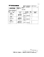
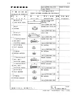
4.3 RP Board RP-26
The RP Board RP-26, which providesvideo plotter functions, consists of a circuit
board and a card drive both of which are accommodated in the display unit of the
FR-2105 series radar.
Table top/console type
Necessary Parts: RP-26-T-2E (008-485-520)
e
m
a
N
e
p
y
T
y
t
Q
.
o
n
e
d
o
C
d
r
a
o
b
P
R
8
9
2
0
P
4
1
1
0
4
6
-
7
8
4
-
8
0
0
.
y
s
s
a
e
s
a
c
d
r
a
C
–
1
–
B
w
e
r
c
s
d
a
e
h
n
a
P
W
0
0
7
2
C
8
x
4
M
4
5
4
4
-
1
8
8
-
0
0
0
B
w
e
r
c
s
d
a
e
h
n
a
P
W
0
0
7
2
C
8
x
3
M
2
4
0
4
-
1
8
8
-
0
0
0
A
w
e
r
c
s
d
a
e
h
n
a
P
W
0
0
7
2
C
5
x
6
.
2
M
2
3
7
9
-
0
0
8
-
0
0
0
r
e
h
s
a
w
k
c
o
l
d
e
h
t
e
e
T
)
h
t
e
e
t
e
d
i
s
t
u
O
(
W
1
9
1
5
C
4
M
1
6
0
5
-
4
6
8
-
0
0
0
.
y
s
s
a
e
l
b
a
C
2
5
-
A
-
A
-
D
0
0
1
-
6
F
I
H
1
3
5
5
-
7
3
1
-
0
0
0
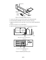
1. Lift the monitor and fix it with the stay. Refer to Chapter 1 for instructions.
2. Remove the right arm cover from the control head.
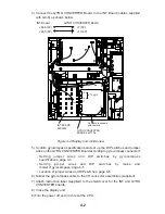
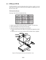
3. Fasten the card case to the right arm cover as follows:
a) Fasten the ground wire with an M4x10 screw and washer (supplied) as shown
below.
b) Fasten the arm cover to the card case with three M4x8 screws (supplied).
Arm cover (right)
Panhead screw
M4X10
Panhead screw
M4X8 3 pcs.
Washer
M4
Card case
Ground wire
Figure 4-9 Fastening the card case to the right arm cover
Summary of Contents for FR-2165DS
Page 1: ...MARINE RADAR MODEL FR 2165DS...
Page 61: ......
Page 62: ......
Page 63: ......
Page 64: ......
Page 65: ......
Page 66: ......
Page 67: ......
Page 68: ......
Page 69: ......
Page 70: ......
Page 71: ......
Page 72: ......
Page 73: ......
Page 74: ......
Page 75: ......
Page 76: ......
Page 77: ......
Page 78: ......
Page 79: ......
Page 80: ......
Page 81: ......
Page 82: ......
Page 83: ......
Page 84: ......
Page 85: ......
Page 86: ......
Page 87: ......
Page 88: ......
Page 89: ......
Page 90: ......
Page 91: ......
Page 92: ......


