1-14
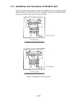
7. Plug in two connectors of connection cable (P412, J583: See illustration on the
previous page.)
8. Lower the monitor.
9. Attach the monitor front cover (option) to the place the panel cover have been,
using the screw for the panel cover.
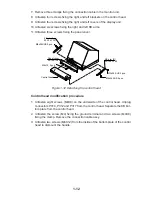
10.Attach rubber to feet to the bottom of the keyboard if the keyboard is not going
to be permanently fixed. To fix the keyboard to a desired location, fasten the KB
fixing plate to the keyboard and desired location with two upset screws (M5X25,
formerly used to fasten KB arms) and two tapping screws (
φ
6.5, local supply)
as below.
KB Fixing Plate
KB Fixing
Plate
CONTROL HEAD TOP VIEW
CONTROL HEAD
SIDE VIEW
M5X25
Upset
Screw
φ
6.5
Tapping
Screw
Figure 1-14 How to attach KB fixing plate
11. Set dust cover KB (supplied) on the control head.
Attachment of hood
1. Set two spacers (supplied) to the lower two of the four M5 holes in the CRT
panel.
2. Screw two screws (supplied) into the holes in the hood.
3. Set the bottom of the hood to the screws at the bottom of the CRT panel, and
then fasten the two screws at the top of the hood to the CRT panel.
Summary of Contents for FR-2165DS
Page 1: ...MARINE RADAR MODEL FR 2165DS...
Page 61: ......
Page 62: ......
Page 63: ......
Page 64: ......
Page 65: ......
Page 66: ......
Page 67: ......
Page 68: ......
Page 69: ......
Page 70: ......
Page 71: ......
Page 72: ......
Page 73: ......
Page 74: ......
Page 75: ......
Page 76: ......
Page 77: ......
Page 78: ......
Page 79: ......
Page 80: ......
Page 81: ......
Page 82: ......
Page 83: ......
Page 84: ......
Page 85: ......
Page 86: ......
Page 87: ......
Page 88: ......
Page 89: ......
Page 90: ......
Page 91: ......
Page 92: ......

