background image

 1-4

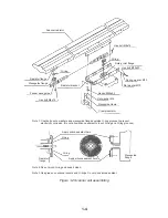
Scanner radiator

Radiator flange

Waveguide flange

Feeder waveguide

Hex bolt M6x16

Radiator bracket

O-ring

Clamp insulator

Waveguide clamp

Flat washer M6

Hex bolt M6x50

Flat washer M10

Spring washer M10

Hex bolt M10x20

Rotary joint flange

O-ring

Hex bolt M6x16

Apply silicone sealant here.

O-ring

Radiator
flange

Apply silicone sealant here.

O-ring

Waveguide
flange

Note 1: Coat bolts, nuts, washers and waveguide flanges outside O-ring grooves to prevent
            electrolytic corrosion. (Do not allow silicone sealant to touch O-ring and O-ring grooves.)
            

Note 2: Do not pinch O-ring and keep it clean.

Note 3: Use grease on scanner covers and O-rings. Do not use silicone sealant.

Figure 1-2 Scanner unit assembling

Summary of Contents for FR-2165DS

Page 1: ...MARINE RADAR MODEL FR 2165DS...

Page 2: ...o c a l A g e n t D e a l e r 9 5 2 A s h i h a r a c h o N i s h i n o m i y a J a p a n T e l e p h o n e 0 7 9 8 6 5 2 1 1 1 T e l e f a x 0 7 9 8 6 5 4 2 0 0 A l l r i g h t s r e s e r v e d Pri...

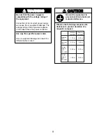
Page 3: ...it may get wet from rain or water splash Water in the display unit can result in fire electrical shock or equipment damage ELECTRICAL SHOCK HAZARD WARNING Radio Frequency Radiation Hazard The radar sc...

Page 4: ...onnector Use only the specified power cable Fire or equipment damage can result if a different cable is used CAUTION Observe the following compass safe distances to prevent deviation of a magnetic com...

Page 5: ...ADJUSTMENT 3 1 Tuning Initialization 3 1 3 2 Accessing Menus for Initialization and Adjustment 3 1 3 3 Adjusting Video Signal Level 3 1 3 4 Heading Alignment 3 2 3 5 Adjusting Sweep Timing 3 3 3 6 Sup...

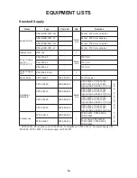
Page 6: ...P C 7 0 9 3 1 3 0 P C 6 1 9 3 1 3 0 P C m 5 1 5 1 4 8 3 0 S e l b a C l a n g i S S E E P A C K I N G L I S T S 0 1 9 9 1 3 0 P C 4 9 3 9 8 0 0 0 0 3 0 1 9 1 3 0 P C 1 0 6 4 1 3 0 P C 7 0 9 3 1 3 0 P...

Page 7: ...i d 3 0 8 1 U R 0 2 4 0 3 0 0 0 0 1 V 0 4 4 r o f V 0 0 1 t i n u y a l p s i d 2 2 5 6 U R 0 1 4 0 3 0 0 0 0 1 V 0 2 2 r o f V 0 0 2 t i n u r e n n a c s 5 0 3 3 U R 8 4 4 0 3 0 0 0 0 1 r e c i e d...

Page 8: ...10 SCANNER UNIT Video Plotter RP 26 RU 1803 440 VAC 1 50 60 Hz SHIP S MAINS POWER SUPPLY UNIT PSU 004 POWER SUPPLY UNIT PSU 001 24 VDC RU 1758 For 220 230 VAC only Gyro Converter GC 8 Gyrocompass RSB...

Page 9: ...gnal cable near other onboard electrical equipment Also avoid running the cable in parallel with power cables A magnetic compass will be affected if placed too close to the scanner unit Observe the fo...

Page 10: ...ration and rolling exerting excessive levels of stress at the base of the radiator which can damage the radiator To prevent this relocate the scanner unit or if relocation is not possible reinforce th...

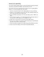
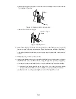
Page 11: ...tary joint flange Make sure the O ring is not pinched during assembling 3 Secure the feeder waveguide to the rotary joint flange with four M6x16 hex bolts 4 Fix the feeder waveguide on the radiator br...

Page 12: ...Hex bolt M6x16 Apply silicone sealant here O ring Radiator flange Apply silicone sealant here O ring Waveguide flange Note 1 Coat bolts nuts washers and waveguide flanges outside O ring grooves to pre...

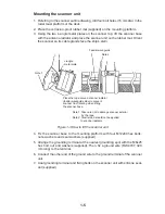
Page 13: ...r waveguide side to prevent scanner from rotating when lifting the scanner base Note 1 Take care not to damage scanner exterior by the rope Note 2 Tensile load should not be applied to scanner radiato...

Page 14: ...at with silicone sealant after attaching ground wire Ground wire Scanner body Welding Hex bolt FW SW Hex nut Ground wire Ground wire Hex nut SW FW FW Hex bolt Arrange ground terminal at nearest ground...

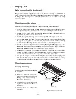
Page 15: ...mally experienced on the ship If necessary reinforce the mounting location Determine the mounting location considering the length of the signal cable be tween the scanner unit and the display unit and...

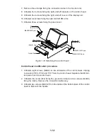
Page 16: ...r until the CRT is horizontal fix the stay as follows a Raise the stay as shown below Stay HORIZONTAL WARNING Possibility of injury Hold handle when mounting display unit Display unit may fall Lock st...

Page 17: ...spanner supplied You cannot fasten the display unit at the rear fixing holes while the monitor is raised 7 Retract the stay and lower the monitor 8 Fasten the display unit to the mounting locations at...

Page 18: ...gh the deck referring to the outline drawing at end of this manual 2 Open the front cover 3 Fix the equipment with M12 bolts nuts and washers 4 Hoist the console to the deck by using the eye bolts att...

Page 19: ...e t a l P e l d n a H 2 3 6 1 4 4 1 3 0 1 0 4 0 8 6 2 0 0 1 Display unit modification procedure 1 Raise the monitor unit referring to procedure for tabletop mounting on page 1 7 2 Unplug two connecto...

Page 20: ...cover 03 144 1345 M4x10 3 pcs Control head M5x25 SUS 4 pcs M5x25 SUS 3 pcs KB arm R 03 144 1342 Figure 1 12 Detaching the control head Control head modification procedure 1 Unfasten eight screws M4X8...

Page 21: ...able assy in kit J 3 1 7 u n d e r s i d e KB Fixing Plate Figure 1 13 Control head Connection of display unit to control head 1 Attach the handle to the handle plate using the screws for the handle a...

Page 22: ...esired location with two upset screws M5X25 formerly used to fasten KB arms and two tapping screws 6 5 local supply as below KB Fixing Plate KB Fixing Plate CONTROL HEAD TOP VIEW CONTROL HEAD SIDE VIE...

Page 23: ...or horizontal position For the console mount display unit the PSU 004 can be installed inside the console However select a dry and well ventilated location and observe the compass safe distances belo...

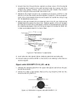
Page 24: ...areful not to nick the braided shield Approx 550 mm Anti corrosive vinyl sheath Armor Approx 540 mm Inner shield Outer shield Figure 2 1 Fabricating the signal cable S03 84 2 Turn off the ANT MOTOR SW...

Page 25: ...ner core and fold back conductor as illustrated below Shorten the shield leaving approx 45 mm Fit crimp on lugs to the conductor FVD1 25 3 Red and braided shield FV1 25 M3 Red Coaxial cable 2C 2V 50 m...

Page 26: ...blue 4 to each conductor Make sure each connection is secure both electrically and mechanically 7 Lead cable into cable gland tighten clamping gland and seal with putty 8 Connect the conductors to STB...

Page 27: ...ng plate 2 TB fixing plate 1 Cable clamp 3 pcs Cable gland STB 3 STB 2 Photo No 2919 Figure 2 6 Scanner unit port side view Ground terminal Photo No 2918 Figure 2 7 Scanner unit starboard side view Tx...

Page 28: ...move insulation of cores by about 10 mm Fix crimp on lugs to the cores and armor 5 Cover the armor with vinyl tape leaving the portion which will lie inside the cable clamp untaped 40 mm Lay this part...

Page 29: ...8 Hex bolt M5X12 SUS 2 pcs Hex bolt M5X35 SUS 2 pcs Hex bolt M5X35 SUS 2 pcs A Rear clamp base B Power clamp Aluminum C Signal clamp Aluminum D Rear clamp plate B Power clamp Aluminum C Signal cable A...

Page 30: ...through the cable clamp at the rear of the console and ground their shields in the cable clamp For signal cable remove vinyl sheath where cable lies in cable clamp Fasten cables with cable ties Close...

Page 31: ...J445 J449 J465 J455 J466 J454 J450 J462 J456 J453 J451 J458 J457 J452 J442 J443 J444 J463 Connect coax cable here 1 Fasten TX HV line to 1 terminal To fasten 1 Slide terminal 2 Lift terminal to remov...

Page 32: ...F 0 8 D M F 1 1 0 r o f t i n u y a l p s i D 1 s e i r e s 5 0 1 2 R F d e s u e b n a c r a d a r y a l p s i d e v a l s s a t i n u g n i r a e b g n i d a e H r e g g i r t x T o e d i v l a n g...

Page 33: ...Board and change the power fuses inside the display unit as shown in the table below according to ship s mains The figure below shows the location of the power fuses and the jumper wires on the PTU Bo...

Page 34: ...n n o C g u L n o p m i r C 9 o t 1 2 B T P d e R 3 M 5 2 1 V F 6 1 o t 0 1 1 B T P e u l B 4 2 V F Power Cable 250V DPYC 3 5 Core S 3 52 mm 2 4 mm Armor Vinyl sheath SECTIONAL VIEW 300 mm Figure 2 1...

Page 35: ...y K3 Relay K1 TB PTB12 TB PTB13 TB PTB11 TB PTB14 Photo No 3148 Figure 2 17 Power supply unit PSU 004 The type and rating of the thermal relay K2 are as below s p i h S s n i a M t i n U r e n n a c S...

Page 36: ...ed The rectifier unit can be installed in any dry well ventilated place Connect AC ship s mains to the rectifier as below 24 VDC output AC ship s mains Connections for 100 VAC ship s mains 24 VDC outp...

Page 37: ...g and holding down the HL OFF key Restoring default settings 1 Press RADAR MENU 0 0 0 2 0 0 0 to display the INITIAL SETTING 4 menu 2 Press the 0 key to select FACTORY DEFAULT 3 3 Adjusting Video Sign...

Page 38: ...nner mounted error to port HDG SW advanced Picture appears deviated clockwise Apparent position of target 000 010 020 030 040 050 060 070 080 090 100 110 120 130 140 150 160 170 180 190 200 210 220 23...

Page 39: ...MENU 0 0 0 2 3 to select TIMING ADJ on the INITIAL SETTING1 menu 2 Transmit on the 0 25 nm range 3 Adjust radar picture controls to display picture properly 4 Select a target echo which should be disp...

Page 40: ...tch in the display unit PM ON OFF TUNE DEGAUSS ERROR ANTENNA switch ANTENNA Figure 3 5 Antenna switch in tuning compartment 7 Connect a multimeter set to the 10 VDC range between J829 1 and 2 in the s...

Page 41: ...the length of the cable between the scanner unit and the power supply unit is more than 60 meters the magnetron heater voltage may not reach the lower limit due to voltage drop If this is the case inc...

Page 42: ...PLAY MAIN SUB 9 SECTOR BLKG OFF ON 000 000 000 000 0 INITIAL SETTING 3 INITIAL SETTING 3 1 INITIAL SETTING 2 2 TRAILS RESTART OFF ON 3 ECHO AVG W O GYRO OFF ON 4 HEAD UP TB SCALE DEG 16POINT 5 CTR ECH...

Page 43: ...p vector compass or course KEY BEEP Turns key response beep on or off SCANNER STOPPED Set to ST BY in normal use TX enables transmission state without scanner rotation VIDEO SIG Set to ANLG analog for...

Page 44: ...MODEL Selects radar model TYPE Selects specification of radar Select R for R type G for IMO type CTR STC CURVE Selects level of STC affect Low Medium or High RJ 7 RJ 8 Selects which Interswitch unit...

Page 45: ...llation and connection of the GYRO CONVERTER Board Necessary Parts GC 8 2 008 446 520 e m a N e p y T y t Q o N e d o C d r a o B r e t r e v n o C o r y G 6 0 1 1 P 4 6 1 0 2 2 2 1 4 4 0 0 s w e r c...

Page 46: ...t up the DIP switches and jumper wires on the GYRO CONVERTER Board according to gyrocompass connected Setting jumper wires and DIP switches by gyrocompass specifications page 4 3 Setting jumper wires...

Page 47: ...oard DIP switch jumper wire settings Default setting The default setting of all DIP switches is off and all jumpers wire are set to 1 Note that jumper wire JP1 is set at 1 2 and 3 In those settings th...

Page 48: ...J e g a t l o v r o t a t S 2 2 W S 3 2 W S 2 P J C A V 5 4 o t V 0 2 N O 2 r o C A V 5 4 o t V 0 2 C D V 0 6 o t V 0 2 N O F F O 2 C A V 0 7 o t V 0 3 F F O 2 C A V 0 9 o t V 0 4 N O 1 r o C A V 5 4...

Page 49: ...o v r o t a t S x 0 6 3 F F O F F O F F O F F O F F O F F O F F O F F O F F O F F O F F O 1 3 2 2 2 1 1 c e m i k o T y r r e p S e p y t 1 1 2 1 S E 2 0 1 1 0 1 T L G 7 0 1 K 6 0 1 3 0 1 s u o n o r...

Page 50: ...itch J10 Data output port 4 J11 Data output port 5 J12 Data output port 6 Figure 4 4 GYRO CONVERTER Board Setting the heading readout on the radar display Confirm that the gyrocompass is giving a reli...

Page 51: ...N e p y T y t Q o n e d o C d r a o b P R A B 2 0 0 9 P 8 1 1 0 5 6 3 7 4 8 0 0 Installation of the ARP board 1 Remove the bottom cover of the display unit by unfastening four screws 2 Set the ARP Boa...

Page 52: ...Board so the multimeter reads between 0 09 and 0 14 VDC 4 Set controls and switches as below GAIN fully clockwise max Interference rejector OFF Range 24 nm Echo stretch OFF 5 Press RADAR MENU 0 0 0 0...

Page 53: ...mit state Confirm that LEDs CR9 CR10 CR11 CR12 CR15 and CR16 on the ARP Board are off If ship s speed is zero or other signal is not being input correspond ing LED will light S1 CR16 LOG CR15 GYRO CR9...

Page 54: ...e r c s d a e h n a P W 0 0 7 2 C 5 x 6 2 M 2 3 7 9 0 0 8 0 0 0 r e h s a w k c o l d e h t e e T h t e e t e d i s t u O W 1 9 1 5 C 4 M 1 6 0 5 4 6 8 0 0 0 y s s a e l b a C 2 5 A A D 0 0 1 6 F I H...

Page 55: ...ase See page 4 7 for the location of the pcb card case 7 Run the connector from the card case in front of the GYRO CONVERTER Board 8 Plug the connector in J1 on the RP Board 9 Fasten the ground wire f...

Page 56: ...H n a P W 0 0 7 2 C 8 x 4 M 1 5 4 4 1 8 8 0 0 0 B w e r c S d a e H n a P W 0 0 7 2 C 8 x 3 M 2 4 0 4 1 8 8 0 0 0 A w e r c S d a e H n a P W 0 0 7 2 C 5 x 6 2 M 2 3 7 9 0 0 8 0 0 0 1 Lift the monitor...

Page 57: ...e top slot of the pcb card case 7 Run the connector from the card case in front of the GYRO CONVERTER Board 8 Plug the connector in J1 on the RP Board 9 Fasten the ground wire from the connector at th...

Page 58: ...4 1 8 8 0 0 0 y s s A r o t c e n n o C A A 0 0 3 L P 3 H V 2 4 1 0 1 4 1 0 0 0 1 Lift the monitor See Chapter 1 for instructions 2 Fasten the PM Board 03P9225 to the location shown below with three...

Page 59: ...nitor and fix it with the stay See page 1 5 for instructions 2 Unfasten four screws to dismount the shield cover for the INT Board 3 Fasten the ALARM Board to the display unit with four pan head screw...

Page 60: ...rew M4X12 Cable Band HP 3N INT Board 03P9252 NH Connector 03 1990 9 9P Pass cable through here Existing cable tie Figure 4 16 Display unit inside view 20 mm Shrink Tubing HOW TO INSULATE THE POWER CAB...

Page 61: ......

Page 62: ......

Page 63: ......

Page 64: ......

Page 65: ......

Page 66: ......

Page 67: ......

Page 68: ......

Page 69: ......

Page 70: ......

Page 71: ......

Page 72: ......

Page 73: ......

Page 74: ......

Page 75: ......

Page 76: ......

Page 77: ......

Page 78: ......

Page 79: ......

Page 80: ......

Page 81: ......

Page 82: ......

Page 83: ......

Page 84: ......

Page 85: ......

Page 86: ......

Page 87: ......

Page 88: ......

Page 89: ......

Page 90: ......

Page 91: ......

Page 92: ......

Reviews: