background image

3. WIRING 


3-6 


Armor

4P cable

Copper strap

Vinyl tape

After clamping cable,
seal cable gland with
putty for watertightness.

Transducer 
cable

Outer shield

*

*

*

*

*

*

*

*

Shield

BLK

RED

BLK

RED

GRN

BLK

RED GRN

BLU

BLU

Clamp vinyl sheath
by cable gland.


Junction box, inside view 


Summary of Contents for CI-88

Page 1: ...RING 3 1 3 1 Wiring the Control Unit 3 1 3 2 Wiring the Transceiver Unit 3 2 3 3 Connecting the Junction Box 3 4 3 4 External Equipment 3 7 4 ADJUSTMENTS 4 1 4 1 INSTALLATION Menu 4 1 4 2 Input Output Data 4 10 4 3 External Noise and Interference Check 4 12 4 4 Setting Output Data 4 15 4 5 DIP Switch Setting 4 16 4 6 Sea Trial Check 4 17 INSTALLATION MATERIALS ACCESSORIES SPARE PARTS A 1 OUTLINE D...

Page 2: ...nual is elemental chlorine free FURUNO Authorized Distributor Dealer 9 52 Ashihara cho Nishinomiya 662 8580 JAPAN A NOV 2003 Printed in Japan All rights reserved D MAY 09 2017 Pub No IME 72530 D TASU CI 88 0 0 0 1 4 8 0 2 7 1 3 ...

Page 3: ...he specified transducer tank in accordance with the installation instru ctions If a different tank is to be installed the shipyard is solely respon sible for its installation and it should be installed so the tank doesn t strike an object The tank or hull may be damaged if the tank strikes an object Observe the following compass safe distances to prevent intereference to a magnetic compass Transce...

Page 4: ...ii SYSTEM CONFIGURATIONS System configuration ...

Page 5: ...00 070 017 Choose one Between Transceiver and Control units 10 m CP66 01610 000 070 018 20 m CP66 01620 000 070 019 30 m CP66 01630 000 070 020 50 m CP66 01501 006 917 660 1 For transducer unit CP66 01504 006 917 350 1 For transceiver unit CP66 01500 006 917 980 1 For control display unit CP66 01503 006 916 750 1 For control unit Accessories FP02 05100 000 012 474 1 Hood FP02 05101 Spare Parts SP6...

Page 6: ...00 148 498 10 1 Between monitor and control unit 10 m Transducer Casing CI 820 000 069 044 1 For FRP keel flush mount type CI 821 000 069 040 1 CI 822 000 069 042 1 For FRP projection type CI 823 000 069 046 1 For steel vessels w kingston CI 824 000 069 049 1 For steel vessels w kingston CI 825 000 069 060 1 For steel vessels w kingston CI 826 000 069 095 1 For steel vessels w kingston CI 827 000 ...

Page 7: ...its especially the hull unit is very important Poor siting of units or poor cable layout may cause pick up of noise or give interference to other units This chapter presents an overview of how to install the equipment 1 1 Selection of Installation Site for Transducer The performance of the equipment largely depends on the installation of the transducer unit and a very important consideration is th...

Page 8: ... harmonic is within the frequency range of 236 kHz to 252 kHz 244 8 kHz is mounted interference may occur Even if the harmonic is out of the range the risk of interference still exists if the transducer of the CI 88 and other equipment are mounted near one another For this reason separate the transducer of the CI 88 as far as practical from other equipment which have high output power If interfere...

Page 9: ...pment such as a direction finder and radio receiver if it is not grounded properly It is strongly recommended to ground all cables referring to the guidelines below a Separate all units as far as possible from radio equipment b Do not run interconnection cables close to or near radio equipment or its cables c Run the cables in the shortest path practical d Lay the cables on grounded copper plate a...

Page 10: ... or cause electrical shock CAUTION Monitor unit Control unit Fix the ground wires by the two wing nuts at the rear of the units Transceiver unit Fix copper strap w 50 mm to ground studs by the two wing nuts Junction box Ignore the protection grounding label at the fixing location for the copper strap Fix copper strap to ground studs by the two wing nuts Location of ground terminals ...

Page 11: ...e drawings at the back of this manual for details Locate the units out of direct sunlight and hot air The operator should face the bow while viewing the display screen Select a location where the display screen can be easily observed while operating the control unit Keep the unit away from the magnetic field Environmental temperature should be 15 to 55 C Locate the units at the place with minimal ...

Page 12: ... control unit a Dismount the coupling plate from the rear of the monitor unit to separate the monitor unit from control unit b Attach the hanger at the rear of the monitor unit with four binding screws M4x10 1 2 3 4 1 2 3 4 Bracket rear view Monitor unit rear view 3 Grease threads of upset screws M6x16 2 pcs used to fasten the hanger to the mounting base 4 Attach the waterproofing cap MJ A10C supp...

Page 13: ...l unit separately To mount the control unit separately or without the monitor unit one of the following accessories option is required Type FP06 01120 Code No 006 556 260 Name Type Code No Qty Remarks Mounting plate 06 021 2111 100 279 740 1 Bracket 06 021 2112 100 281 880 1 Tapping screw 5x20 000 802 081 2 Hex screw M4x12 000 882 040 4 Hole plug DP 687 000 808 417 2 Type FP66 00601 Code No 006 91...

Page 14: ...control unit with two hex screws M4x12 3 Insert screwdriver from the top of the mounting plate holes and then loosely fasten two hex screws M4x12 Cable entrance hole Cable can be passed this direction Mounting plate Bracket Tapping screws 5X20 Cable Fasten the screws to fix the bracket Bracket Fix with hex screws Set to the hex screws tightened at step 3 Mounting the control unit 4 Attach the cont...

Page 15: ...ng metal CONT port Monitor unit control unit rear view 3 Attach the waterproofing cap MJ A10C supplied as installation materials to the CONT port at the back of the monitor unit 4 Using four tapping screws 5x20 fasten the fixing metal attached at step 2 to the mounting location Monitor unit For flush mounting of the monitor unit the following optional kit is required Type OP06 17 Code No 006 556 3...

Page 16: ... Control unit The following optional kit is necessary Type OP06 18 Code No 006 556 320 Name Type Code No Qty Remarks Fixing metal 06 021 2101 100 279 731 1 Tapping screw 5x20 000 802 840 4 Hex bolt M4x12 000 882 040 2 1 Cut out a hole in the mounting location referring to the outline drawings at the back of this manual 2 Fasten two hex bolts M4x12 to fix the fixing metal to the control unit Hex bo...

Page 17: ...tor three rows of 15 pins max length 15 m locally The monitor connects to the control unit and should satisfy the specifications shown below Note The D sub connector with two rows of 15 pins cannot be used VGA type Analog RGB 0 7 Vpp positive polarity TLL level H V negative polarity ...

Page 18: ...st 50 mm clearance between it and the floor to permit dissipation of heat This unit weights 12 kg Reinforce the mounting area if necessary Leave space around the unit for maintenance and checking Refer to the drawing at the back of this manual Mounting procedure 1 Weld the steel plate shipyard supply with four mounting holes to the bulkhead 2 Use four bolts and nuts M10 supplied as installation ma...

Page 19: ...rature varies greatly since moisture may penetrate the box The box is generally installed above the draft line of the ship and the transducer cable is run inside steel conduit This permits replacement of the transducer without dry docking Even if the junction box is installed below the draft line the conduit is necessary to avoid picking up noise If use of conduit is not possible install the box a...

Page 20: ...sidering the rising angle of the ship s hull Weld the casing in parallel with ship s fore aft line with an accuracy of better than 1 The transducer face should be horizontal at cruising speed Transducer casing Dimple to bow Transducer fixing flange 4 Make a hole for the thru hull pipe in the hull bottom Before welding the thru hull pipe remove the rubber packing from the thru hull pipe Weld the th...

Page 21: ...ng considering the rising angle of the ship s hull so that the transducer face is horizontal The casing should be parallel with ship s fore aft line within 1 and the transducer face should be horizontal at cruising speed 3 Make a hole of 10 to 20 mm in diameter on the stern side of the casing to allow water to penetrate the transducer casing 4 Make a hole for the thru hull pipe on the hull bottom ...

Page 22: ...ide view 9 Fix the fixing flange with the transducer to the casing Take care not to pinch the transducer cable 2 4 2 Sideboard mounting For the sideboard mounting see the TRANSDUCER MOUNTING at the back of this manual The transducer casing and transducer flange can be supplied optionally Prepare the pipe assy and fixing metal at local Stretch the transducer using a lope or chain from the bow so th...

Page 23: ... electronic corrosion Narrow keel Make holes on the keel and transducer casing attach the anti corrosive zinc using the bolts and nuts supplied Wide keel Fasten an end of the earth wire between thru hull pipe and jubilee clip supplied Attach a crimp on lug to another end of the earth wire and then fasten it with the anti corrosive zinc using the bolt and nut supplied as bellow ...

Page 24: ...2 MOUNTING 2 14 This page is intentionally left blank ...

Page 25: ...8 from the transceiver unit as below Transceiver unit Control unit Cable 66S1238 10 20 30 50 m To J11 on the PCP Board 66P3920 3 1 2 Connection with the monitor unit Choose one from the follows to connect the control unit and monitor unit VGA monitor Cable 66S1239 0 3m Control unit VGA monitor Control unit Control monitor units Monitor unit User supply Cable 66S1239 5m or 10m option Cable 66S1242 ...

Page 26: ...on of the clamp KP IN2 KP IN1 Gyro output LOG ALM NMEA2 TX NMEA1 TX Transducer cable NMEA1 RX NMEA2 RX CID to TB3 to TB4 to TB1 3 to TB4 to TB2 Transceiver unit bottom view 1 Fabricating DPYC 2 5 and DPYCY 2 5 Japanese Industrial Standards or equivalent cable Conductor S 2 5 mm φ 2 01 mm 2 DPYC 2 5 DPYCY 2 5 w outer sheath Armor Sheath φ 12 8 mm DPYCY 2 5 14 8 mm Dimensions mm Armor 30 65 FV5 5 S4...

Page 27: ... Wrong connection can damage the transducer NOTE 3 Fabricating of the transducer cable Fold back the shield on the armor Anticorrosive sheath 35 mm Vinyl tube FV1 25 4 Remove the shield Transducer cable 1 Lay armor in cable clamp to ground cable Earth terminal Connect the crimp on lug of the shield wire here 1 2 Brown 4 Blue 6 8 Red 10 Yellow 12 Green 14 Gray 3 5 7 Black 9 White 11 13 BEAM1 BEAM2 ...

Page 28: ...d to the junction box with an extension cable After making the connection seal the cable gland with putty for watertightness 1 Transducer cable 66S1066 no armor Vinyl sheath Cut to suitable length considering location on terminal board Insulation tube FV2 P4 FV5 5 5 FV1 25 4 Junction box Rubber gasket Gland Vinyl tape Vinyl tape See interconnection diagram To internal earth stud Transducer cable n...

Page 29: ...n cable with armor Attach crimp on lugs in the same manner as shown above Fabricate the armor as follows Rubber gasket Gland To earth terminal Wing nut Solder vinyl wire Anticorrosive sheath Armor Clamp vinyl sheath by cable gland 4P cable w armor ...

Page 30: ... Copper strap Vinyl tape After clamping cable seal cable gland with putty for watertightness Transducer cable Outer shield Shield BLK RED BLK RED GRN BLK RED GRN BLU BLU Clamp vinyl sheath by cable gland Junction box inside view ...

Page 31: ...4 1 2 66P3926 PPW8 66P3939 PTR1 10 13 8 1 1 1 1 12 10 3 4 66P3920 PCP 66P3923 PTX8 66P3924 PCN 1 Opener Transceiver unit internal view Conductor S 0 75 mm 1 11 mm 2 TTYCYS 1 Armor Vinyl Sheath 12 1 mm Vinyl Sheath Conductor S 0 75 mm 1 11 mm 2 TTYCY 4S Armor Vinyl Sheath 21 1 mm Vinyl Sheath Shield Shield Sectional views of cable TTYCYS 1 and TTYCY 4S TB1 Use TB1 to transmit receive NMEA and curre...

Page 32: ... the internal shield and sheath TB3 Use TB3 to input output GYRO signal 30 8 to 9 50 280 TTYCY 4S Vinyl tape Armor Cut off the internal shield and sheath TB4 Use TB4 to input output the following signal Alarm signal Output Log signal Output KP signal Input KP signal Output 30 8 to 9 50 200 TTYCYS 1 Vinyl tape Armor Cut off the internal shield and sheath ...

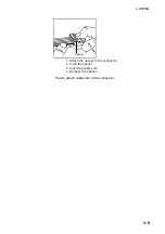
Page 33: ...2 WIRING 3 9 1 Attach the opener to the connector 2 Push the opener 3 Insert the cable core 4 Release the opener Opener How to attach cable core to the connector ...

Page 34: ...3 WIRING 3 10 This page is intentionally left blank ...

Page 35: ...he INSTALLATION menu do the following 1 Press the MENU key 2 Press to move the cursor to the top of the menu 3 Press several times to show the message PRESS ANY FUNC KEY TO OPEN INSTALLATION MENU 4 Press the F1 F2 or F3 key 5 Press 6 Press to select I O I O sub menu ...

Page 36: ... GPS LC NAV DATA Choose source data for calculation of sea tide in the NAV mode SPD Speed data from the GPS navigator is used as ground tracking speed to calculate sea tide L L Position data from the GPS navigator is used as ground tracking speed to calculate sea tide TIME INTERVAL Set the time interval for reading position data to use for calculating speed Effective when NAV DATA above is selecte...

Page 37: ... the NAV mode TIDE OUT INT Choose the output interval for tide data from among 15 and 30 seconds and 1 2 5 and 10 minutes TEMP SENSOR Choose YES if a water temperature sensor is connected to the current indicator 4 1 2 CALIB menu SELECT CHANGE MENU EXIT MENU 1 MENU 2 ALARM INSTALLATION I O CALIB OTHER Shown when CSE CALIB MODE is set to GT or NAV DRAFT 0 0m HEEL ANGLE 0 0 TRIM ANGLE 0 0 GT SPD CAL...

Page 38: ... for aft high state 12 8 12 7 Set to 5 0 when fore side is higher than aft side by five decrees θ GT SPD CALIB Calibrate ship s speed in the ground tracking mode setting range 12 8 12 7 True speed should be calculated at the sea trial Calibration value is obtained as follows Calibration value X 100 True speed True speed CI 88 measured speed WT SPD CALIB Calibrate ship s speed in the water tracking...

Page 39: ...de For details see paragraph 1 6 in the operator s manual 2 Press the MENU key to open the menu 3 Press to place the cursor on the menu title area 4 Press to choose INSTALLATION 5 Press any function key F1 F2 or F3 to unlock the INSTALLATION menu 6 Press to choose the sub menu title area 7 Press or to choose CALIB 8 Press or to choose CSE CALIB MODE 9 Press to choose GT 10 Run the vessel at a spee...

Page 40: ...aph 1 6 in the operator s manual 2 Press the MENU key to open the menu 3 Press to place the cursor on the menu title area 4 Press to choose INSTALLATION 5 Press any function key F1 F2 or F3 to unlock the INSTALLATION menu 6 Press to choose the sub menu title area 7 Press or to choose CALIB 8 Press or to choose CSE CALIB MODE 9 Press or to choose NAV 10 Run the vessel at a speed of about 10 kn for ...

Page 41: ...ey pressed SOUND VELOCITY Choose YES to calibrate sound velocity EXTERNAL KP1 Set distance between transducer of this current indicator and external KP transducer which is connected to the current indicator as an interference source The setting range is 0 0 25 5 m Also set the DIP switch as shown on page 4 14 EXTERNAL KP2 Set distance between transducer of this current indicator and external KP tr...

Page 42: ... depth data internal or external BTM TRACK BEAM Choose sounding beam to use to detect bottom The choices are B beam 1 B 2 B 3 and ALL PULSE LENGTH Choose pulse length to use in the water tracking mode The choices are NORMAL and LONG PWR REDUCTION Choose LOW to reduce output power DEPTH UNIT Choose unit of depth measurement from m or HR ...

Page 43: ... VIETNAM ျမန မာ SIMULATION Turn the simulation mode on or off and choose simulation mode parameters VARIABLE Feeds simulation mode data from the processor to the control unit FIXED Use the user set speed and tide values Procedure 1 Choose VARIABLE or FIXED and then the message Press any function key to execute appears Press any function key to start the simulation mode 2 If you selected FIXED the ...

Page 44: ...e Own ship s position L L GGA RMC RMA GLL Ship s speed VTG RMC RMA Heading HDT HDG HDM Depth DPT DBT NMEA Output Sentences Talker Format Information Interval VD VBW STW SOG 1 s VD VDR Current direction speed 3 s VD VHW STW Heading 1 s VD VTG SOG Course True 1 s VD VLW Trip distance 3 s VD CUR Multiple layered current 3 s NMEA output sentences are changeable as below depending on the NMEA VERSION s...

Page 45: ...aring data 4 Bearing data 57 Depth data 58 Water temperature data 54 LC time difference Priority Information Priority No Positioning data 28 24 Ship s speed bearing data 48 44 Output sentences Data No Information Interval 56 Single layered current data 3 s 66 Current indicator measured speed bearing 3 s 76 Multiple layered current by depth 15 s ...

Page 46: ... the cursor to the top of the screen 3 Press several times to select MENU 1 4 Press several times to select TEST 5 Press to choose GENERAL 6 Press the F1 key If the NL is 5 or more the unit is receiving affects of interference In this case check the following points Grounding of the transducer unit Noise source around the transceiver unit Distance between the transducer cable and ship s power line...

Page 47: ... Flip Flop Circuit H C TP4 CR15 S1 EKP2 11 12 PCN 66P3924 Photo Coupler Interference rejection circuit Check of keying pulse The following keying pulse is required from the interfering equipment 0 V less than 1 V 5 to 15V Keying pulse needed If the level is out of the ratings or KP output circuit is not provided take the measures shown on the next two pages to prevent equipment malfunction Buffer ...

Page 48: ...3924 to ON KP signal is positive logic Set the switch S1 1 on the PCN Board to OFF KP signal is negative logic Set the switch S1 1 on the PCN Board to ON When KP signal is input to KP IN2 set the switch S1 4 on the PCN Board 66P3924 to ON KP signal is positive logic Set the switch S1 2 on the PCN Board to OFF KP signal is negative logic Set the switch S1 2 on the PCN Board to ON Output When output...

Page 49: ... output data among NMEA CIF Current data and Display data Use the jumper block J8 on the PCN Board 66P3924 66P3924 TB3 TB1 TB2 TB4 NMEA CIF NMEA CIF AUX 422 232C J3 J4 J5 J6 J8 J7 ON OFF CR14 CR15 S1 J8 For RS 232C J5 J6 Jumper block Mini connector For RS 422 J5 J6 1 2 3 4 5 1 Inscription on PCB Output data 2 3 4 5 N_TXD CID_DL_TXD NMEA1_TXD NMEA2_TXD DISP_TXD Raw data N value Current data NMEA Sw...

Page 50: ...t 0 05kn Slow When current speed is slow and unstable Minute constant 0 01kn OFF 6 Smoothing filter Yes No OFF 7 Bearing addition Adds bearing information before averaging the ship s speed Adds bearing information after averaging the ship s speed OFF 4 5 2 Speed output interval Select the output interval of ship s speed to display DIP Function OFF ON Default setting 8 Select output interval of shi...

Page 51: ... kn correct it referring to the GT SPD CALIB on page 4 5 Calibrating is not necessary when the error is within 1 0 1 kn 5 Repeat the milepost test several times Record the data in Table 1 6 Record the ship s speed every 10 seconds in table 2 7 Calculate the average ship s speed from the data in the Table 2 to compute accuracy 4 6 2 Current data check Use the ground tracking mode to record the curr...

Page 52: ...orient the same direction If not the interference from other equipment air bubbles and noise may be present Also take into account that interference from air bubbles may occur since there is no load in the milepost test Note 1 When a bearing sensor is connected in lieu of a gyrocompass accurate measurement of current direction is not expected because the bearing data itself is in error Note 2 Note...

Page 53: ...4 ADJUSTMENT 4 19 ...

Page 54: ...0 SHIP S NAME DEPTH m TEST SITE WIND SPEED ms COURSE 00 SHIP S NAME DEPTH m TEST SITE WIND SPEED ms COURSE 10 10 20 20 30 30 40 40 50 50 00 00 10 10 20 20 30 30 40 40 50 50 00 00 10 10 20 20 30 30 40 40 50 50 00 00 10 10 20 20 30 30 40 40 50 50 00 00 10 10 20 20 30 30 40 40 50 50 00 00 ...

Page 55: ...4 ADJUSTMENT 4 21 ...

Page 56: ...4 ADJUSTMENT 4 22 This page is intentionally left blank ...

Page 57: ...ߖࠎ ޕ 691 6 2 5 0 1 5 56 14 0 6 6 19 4 241 7 6 5 22 0 2 1 6 722 4 241 7 6 37 6 5 6 5 C7252 M03 B A 1 C C ODE NO 006 917 660 00 TYPE CP66 01501 略 図 OUTLINE 名 称 NAME 数量 Q TY 用途 備考 REMARKS 番 号 NO 型名 規格 DESCRIPTIONS 1 1 2 INSTALLATION MATERIALS 工事材料表 66AS X 9401 圧着端子 CRIMP ON LUG FV1 25 4 10 000 538 114 00 1 CODE NO FV1 25 4 LF 000 166 666 10 圧着端子 CRIMP ON LUG FV2 4 アオ 5 000 538 118 00 2 CODE NO FV2 4 ...

Page 58: ...17 350 00 TYPE CP66 01504 略 図 OUTLINE 名 称 NAME 数量 Q TY 用途 備考 REMARKS 番 号 NO 型名 規格 DESCRIPTIONS 1 1 3 INSTALLATION MATERIALS 工事材料表 66AS X 9404 圧着端子 CRIMP ON LUG FV5 5 S4 4 000 538 121 00 1 CODE NO FV5 5 S4 LF 000 166 750 10 アース板 COPPER STRAP WEA 1004 0 1 500 310 040 00 2 CODE NO WEA 1004 0 ROHS 500 310 040 10 略図の寸法は 参考値です DIMENSIONS IN DRAWING FOR REFERENCE ONLY FURUNO ELECTRIC CO LTD 型式 コード番号が2段の...

Page 59: ...名 称 NAME 数量 Q TY 用途 備考 REMARKS 番 号 NO 型名 規格 DESCRIPTIONS 1 1 3 ACCESSORIES 付属品表 02FJ X 9508 トリツケダイ MOUNTING BASE 02 127 1301 1 1 100 285 141 00 1 CODE NO 02 127 1301 1 ROHS 100 285 141 10 ハンガー BRACKET 02 127 1302 1 1 100 285 151 00 2 CODE NO 02 127 1302 1 ROHS 100 285 151 10 トラスタッピンネジ 1シュ SELF TAPPING SCREW 5X20 SUS304 4 000 162 608 10 3 CODE NO バインドセムスF WASHER BINDING HEAD SCREW M4X10 C2700...

Page 60: ...Y 略図の寸法は 参考値です DIMENSIONS IN DRAWING FOR REFERENCE ONLY 略図の寸法は 参考値です DIMENSIONS IN DRAWING FOR REFERENCE ONLY FURUNO ELECTRIC CO LTD A 7 C1316 F03 D 1 01 6 2 2 ޓޓ 176 0 ฬ ޓޓ 0 ᢙ 3 6 ㅜ㧛 4 4 5 ภ 01 ဳฬ㧛ⷙᩰ 5 4 26 105 5514 5 ઃዻຠ 5 㩎㩡㩇㩊㨹㩕㩩㩧㩒㩆㩨 㩆㨷 5 6 22 0 5 4 9 575 1 01 㩖㩨㩡㩃㨹㩎 4 6 41 5 1 01 㧗㩔㩨㨼㩧㩎㩨㩈㩛㩇 0 4 5 4 9 9 4 㩕㩡 1 01 㧔 ߩኸᴺߪ ޔ ෳ ୯ߢߔ ޓޕ 05 105 0 4 9 0 14 4 4 0 10 㧕 㧲㨁㧾㨁㧺㧻 ޓ 㧱㧸㧱㧯㨀㧾㧵㧯 ޓ 㧯㧻 ޓ 㧚㧘㧸㨀㧰 ဳᑼ ...

Page 61: ...000 162 939 10 5 CODE NO 略図の寸法は 参考値です DIMENSIONS IN DRAWING FOR REFERENCE ONLY FURUNO ELECTRIC CO LTD 型式 コード番号が2段の場合 下段より上段に代わる過渡期品であり どちらかが入っています なお 品質は変わりませ ん TWO TYPES AND CODES MAY BE LISTED FOR AN ITEM THE LOWER PRODUCT MAY BE SHIPPED IN PLACE OF THE UPPER PRODUCT QUALITY IS THE SAME C1316 F01 H A 9 C C ODE NO 006 556 200 TYPE SP06 01101 ITEM NO NAME OF PART OUTLINE DWG NO OR PER SET PER VES...

Page 62: ...O 66AR X 9301 1 1 ヒューズ FGBO A 5A AC125V 3 FUSE 000 549 064 00 1 FGB0 A 125V 5A PBF 000 155 853 10 1 1 MFR S NAME FURUNO ELECTRIC CO LTD DWG NO 略図の寸法は 参考値です DIMENSIONS IN DRAWING FOR REFERENCE ONLY C7245 P01 A 型式 コード番号が2段の場合 下段より上段に代わる過渡期品であり どちらかが入っています なお 品質は 変わりません TWO TYPES AND CODES MAY BE LISTED FOR AN ITEM THE LOWER PRODUCT MAY BE SHIPPED IN PLACE OF THE UPPER PRODUCT QUALITY IS THE SAME A...

Page 63: ...Takahashi T Y Hatai D 1 ...

Page 64: ...Y Hatai D 2 ...

Page 65: ...Y Hatai D 3 ...

Page 66: ...22 Mar 2011 Y NISHIYAMA D 4 ...

Page 67: ...Takahashi T Y Hatai D 5 ...

Page 68: ...D 6 19 Mar 2015 H MAKI ...

Page 69: ...Takahashi T Y Hatai D 7 ...

Page 70: ...D 8 ...

Page 71: ...Dec 19 03 D 9 ...

Page 72: ...D 10 ...

Page 73: ...Dec 19 03 D 11 ...

Page 74: ...D 12 ...

Page 75: ...Feb 22 05 D 13 ...

Page 76: ...Feb 22 05 D 14 ...

Page 77: ...Feb 22 05 D 15 ...

Page 78: ...Feb 22 05 D 16 ...

Page 79: ...Nov 15 05 D 17 ...

Page 80: ...29 May 2014 H MAKI D 18 ...

Page 81: ...D 19 ...

Page 82: ...D 20 Nov 27 03 ...

Page 83: ... 15 VS_N 1 2 3 4 5 6 7 8 9 10 66S1239 0 3m 0V GND YS GND GND GND GND HS_N R G B GND 1 2 3 4 5 12 13 19 6 14 15 16 17 18 25 12VA VS_N 12VA XM2A 2501 1 66S1239 5 10m 2 表示部 MONITOR UNIT MU 100C D SUB15P 1 2 3 4 5 6 7 8 9 10 66S1243 0 3m 3 1 66P3928 CN A1 J2 XH 10P CN B1 D SUB25P ALARM 警報 KP IN KP OUT KP IN 200P NM LOG PULSE ログパルス 方位データ BEARING DATA AD 10 CURRENT LOOP AUX 66P3924 3 4 CN C7 FL1 WEA 100...

Reviews: