3. WIRING
3-2
3.2
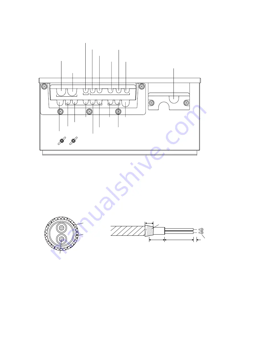
Wiring the Transceiver Unit
Gyro
input
Power cable
LOG200_1
LOG200_2
KP. OUT
AUXTX*
2
Control unit cable (66S1238)
ON_OFF*
1
*1: Contact alarm signal
*2: CIF/NMEA/Current
*3: When connecting the cable from the junction box, reverse the direction of the clamp.
KP.IN2
KP. IN1
Gyro
output
LOG-ALM
NMEA2
TX
NMEA1 TX
Transducer cable
NMEA1 RX
NMEA2 RX
CID
to TB3
to TB4
to TB1
*
3
to TB4
to TB2
Transceiver unit, bottom view
1) Fabricating DPYC-2.5 and DPYCY-2.5 (Japanese Industrial Standards) or equivalent
cable
Conductor
S = 2.5 mm
φ
= 2.01 mm
2
DPYC-2.5
(DPYCY-2.5: w/outer sheath)
Armor
Sheath
φ
=
12.8 mm
(DPYCY-2.5:
14.8 mm)
Dimensions: mm
Armor
30
65
FV5.5-S4
Vinyl tape
20
7
Power cable DPYC-2.5 or DPYCY-2.5
Summary of Contents for CI-88
Page 4: ...ii SYSTEM CONFIGURATIONS System configuration ...
Page 24: ...2 MOUNTING 2 14 This page is intentionally left blank ...
Page 34: ...3 WIRING 3 10 This page is intentionally left blank ...
Page 53: ...4 ADJUSTMENT 4 19 ...
Page 55: ...4 ADJUSTMENT 4 21 ...
Page 56: ...4 ADJUSTMENT 4 22 This page is intentionally left blank ...
Page 63: ...Takahashi T Y Hatai D 1 ...
Page 64: ...Y Hatai D 2 ...
Page 65: ...Y Hatai D 3 ...
Page 66: ...22 Mar 2011 Y NISHIYAMA D 4 ...
Page 67: ...Takahashi T Y Hatai D 5 ...
Page 68: ...D 6 19 Mar 2015 H MAKI ...
Page 69: ...Takahashi T Y Hatai D 7 ...
Page 70: ...D 8 ...
Page 71: ...Dec 19 03 D 9 ...
Page 72: ...D 10 ...
Page 73: ...Dec 19 03 D 11 ...
Page 74: ...D 12 ...
Page 75: ...Feb 22 05 D 13 ...
Page 76: ...Feb 22 05 D 14 ...
Page 77: ...Feb 22 05 D 15 ...
Page 78: ...Feb 22 05 D 16 ...
Page 79: ...Nov 15 05 D 17 ...
Page 80: ...29 May 2014 H MAKI D 18 ...
Page 81: ...D 19 ...
Page 82: ...D 20 Nov 27 03 ...


