3-1
3. WIRING
See the interconnection diagram at the back of this manual.
3.1
Wiring the Control Unit
3.1.1
Connection with the transceiver unit
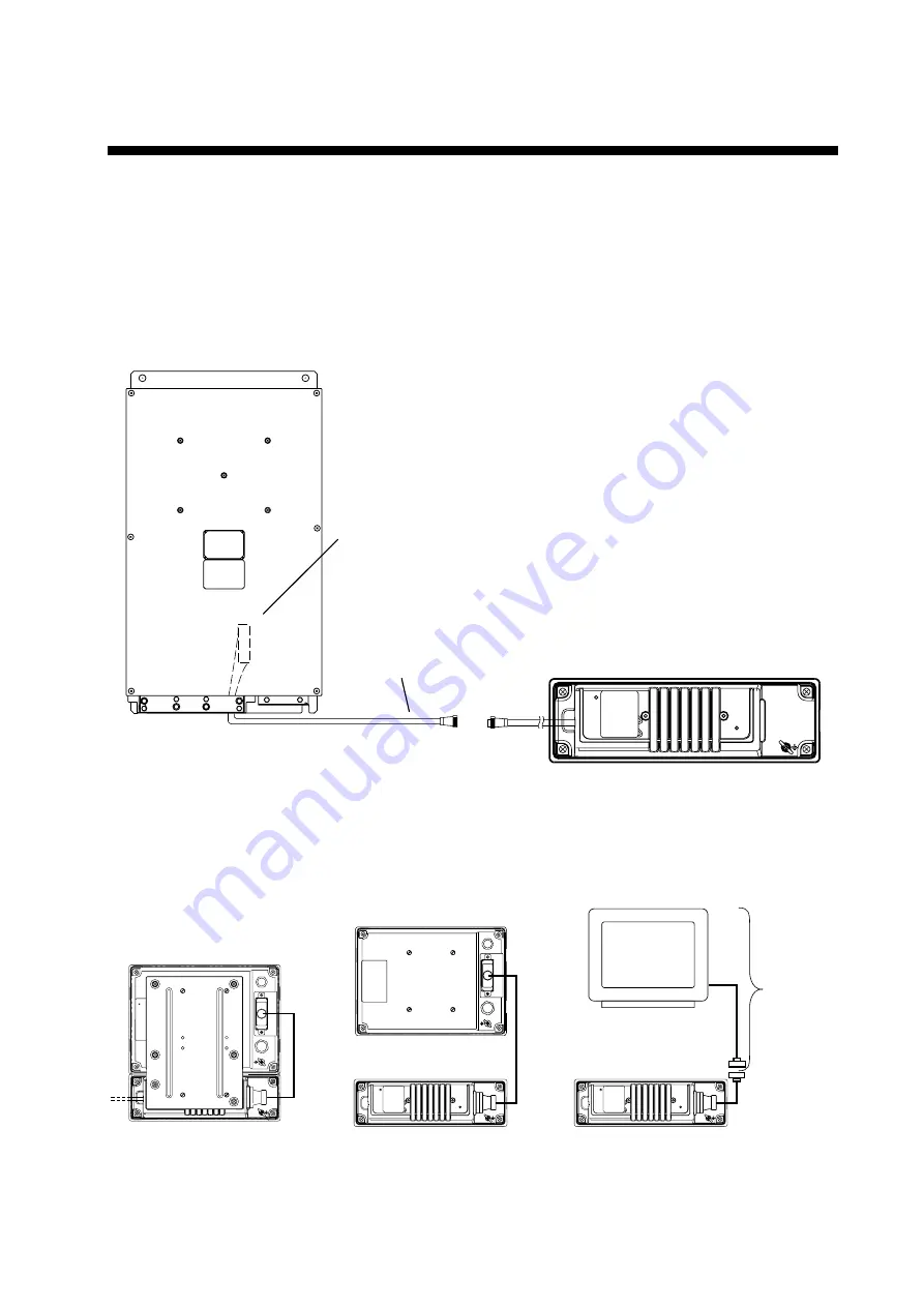
Attach the connector of the control unit to the cable (66S1238) from the transceiver unit as
below.
Transceiver unit
Control unit
Cable 66S1238
10/20/30/50 m
To J11 on the
PCP Board 66P3920
3.1.2
Connection with the monitor unit
Choose one from the follows to connect the control unit and monitor unit (VGA monitor).
Cable
66S1239
0.3m
Control unit
VGA monitor
Control unit
Control/monitor units
Monitor unit
User supply
Cable
66S1239
5m or
10m
(option)
Cable
66S1242
0.3 m
Summary of Contents for CI-88
Page 4: ...ii SYSTEM CONFIGURATIONS System configuration ...
Page 24: ...2 MOUNTING 2 14 This page is intentionally left blank ...
Page 34: ...3 WIRING 3 10 This page is intentionally left blank ...
Page 53: ...4 ADJUSTMENT 4 19 ...
Page 55: ...4 ADJUSTMENT 4 21 ...
Page 56: ...4 ADJUSTMENT 4 22 This page is intentionally left blank ...
Page 63: ...Takahashi T Y Hatai D 1 ...
Page 64: ...Y Hatai D 2 ...
Page 65: ...Y Hatai D 3 ...
Page 66: ...22 Mar 2011 Y NISHIYAMA D 4 ...
Page 67: ...Takahashi T Y Hatai D 5 ...
Page 68: ...D 6 19 Mar 2015 H MAKI ...
Page 69: ...Takahashi T Y Hatai D 7 ...
Page 70: ...D 8 ...
Page 71: ...Dec 19 03 D 9 ...
Page 72: ...D 10 ...
Page 73: ...Dec 19 03 D 11 ...
Page 74: ...D 12 ...
Page 75: ...Feb 22 05 D 13 ...
Page 76: ...Feb 22 05 D 14 ...
Page 77: ...Feb 22 05 D 15 ...
Page 78: ...Feb 22 05 D 16 ...
Page 79: ...Nov 15 05 D 17 ...
Page 80: ...29 May 2014 H MAKI D 18 ...
Page 81: ...D 19 ...
Page 82: ...D 20 Nov 27 03 ...


