1/25/2016
Page | 20
DGOI-C 64 ASSEMBLY INSTRUCTIONS
C16AK0001, Issue 1
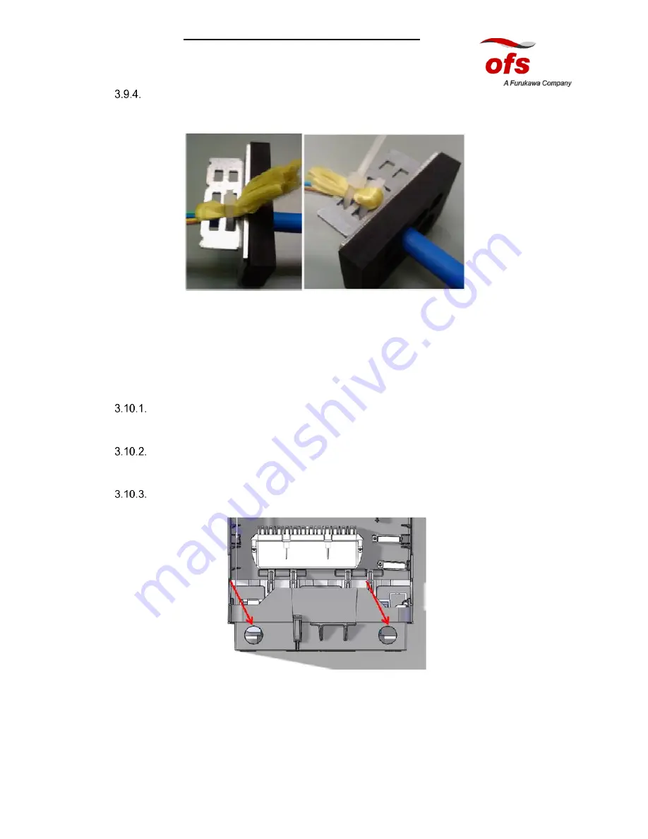
Go around the metal support and pass through the bracket holes. The assembly should
appear as shown in Fig. 37;
Fig.37
NOTE: Fasten a cable tie to secure the yarn. Trim the excess of the cable ties.
3.10.
Installing the cable gland
If necessary, decide which of the two entry locations the gland will be installed.
After the determination of inputs and outputs cable locations, position the cable gland and
anchoring supports for FRP
Remove one of the plastic knock-out shown in Fig. 38 (use a screwdriver). Smooth the
edges of the opening with sandpaper
Insert the cable glands
Fig. 38


