


ASD-120 SEQUENCED POWER DISTRO
8
To reconnect a wire, grasp it by the terminal and pull straight up. Then reposi-
tion it over an unused Fast-On male terminal on the appropriate buss bar and push
down firmly. Wire the loads in accordance with Table 3.
5. Tighten clamp and close unit: Tighten the cable strain relief clamp firmly. If
you are using a cable, make sure about a half inch of the outer jacket extends
beyond the clamp into the unit. If you are using a wire bundle, it is a good idea to
wrap the bundle with several layers of heat shrink tubing or other sturdy material at
the point where the clamp tightens, to minimize the likelihood that the clamp will cut
into the insulation of the individual wires. Review your remote control options and
set control jumpers as required (see Table 3). Replace the top cover. This com-
pletes the internal wiring of the ASD-120.
6. Terminate source end of cable or wire bundle: As mentioned in item 2
above, the most common cable termination is to break the ends out as pigtails and
leave its hookup to the house electrician in each venue. In some circumstances, a
suitable connector may be provided at the power source and the cable can be
terminated with a mating connector. Often these will be Cam-Lok® or similar con-
nectors for each individual conductor.
If you want to provide a way to disconnect the cable from the ASD-120 for
separate storage or shipment, one good way is to permanently attach a very short
cable to the ASD-120 and terminate it with Cam-Lok, Meltric, or similar high-current
connectors. A long cable with mating Cam-Loks would then be prepared which
could easily be disconnected and stored. A good source for custom made high
power cables is “J” Custom Supply, telephone 1-800-226-5657 (1-800-CAM-LOKS).
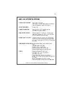
7. Set internal jumpers to suit your application: See Table 4 on page 10.
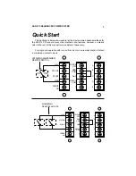
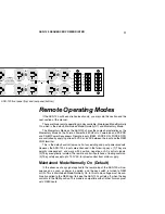
Controlling On/Off Sequence
A normal, time-delayed on or off sequence may be initiated in either of two
ways: locally, via the front panel key switch, or remotely, via a remotely located
maintained or momentary switch connected to the ASD-120’s rear panel terminal
strip. In addition, the behavior of any individual circuit may be overridden by its
corresponding front panel ON/SEQ/OFF toggle switch.
The ASD-120’s control circuits turn on the outlets in order from A to F when
sequencing on, and turn the outlets off in the reverse order from F to A when se-
quencing off. The time for each step is internally adjustable with a trim pot, with a
range of 0.2 to > 12 seconds per step. (Total time for the entire sequence is from 1
second to > 1 minute).
Local control: Turning the key to the ON (or possibly REM) position initiates an
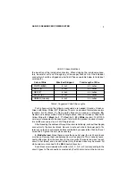
Table 3, Dividing The Load
Input Color Cable
Buss Bar
Circuits
120V or 240V
Black
X
A, C, E
Red
Y
B, D, F
208V 3-ph
Black
X
A, D
Red
Y
B, E
Blue or Orange
Z
C, F