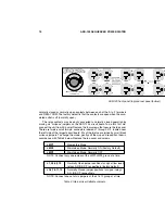
ASD-120 SEQUENCED POWER DISTRO
12
Internal jumpers allow selection of either of two other optional modes, as de-
scribed below. Please also see Table 4, Internal User Settable Jumpers, on page
10.
Maintained Mode/Normally Off
This mode is just the reverse of the Maintained Mode/Normally On mode. The
ASD-120’s outlets stay off until voltage is applied to the REM input. Voltage must
be continually applied to keep the unit on, when the key switch is in the REM posi-
tion. This setting will be useful to interface to other brands of controller that have
positive control logic (i.e. they put out a signal to indicate that attached gear should
turn on). In addition, since the REM inputs are optically isolated, and designed to
accept up to 130 VAC, this mode allows the ASD-120 to sequence on if some other
source of AC line voltage is turned on.
Momentary Mode
In Momentary Mode, the ASD-120 has “memory” — it only needs a momentary
signal to change its state from on to off, or off to on. When first plugged in (or after
power is lost and reapplied for any reason) the “memory” state is off. It will stay off
until sequenced on by the front panel START ON/OFF SEQUENCE pushbutton or
a momentary connection of the REM IN terminal to a voltage source of at least ± 5
VDC or 6 VAC (130V max). The sequence starts on the rising edge of the signal.
The rear panel +12V output may be used as a trigger source. This is further ex-
plained in the section “Setup for Remote Operation” below.
Once the ASD-120 is on (or is sequencing on), applying voltage momentarily to
the REM input starts switching the ASD-120 off, in descending sequence. Pushing
the START ON/OFF SEQUENCE button on the front panel is effectively the same
as applying a signal to the REM input (although the actual connection is applied to
an internal node, not to the REM terminal on the rear barrier strip).
In Momentary Mode there are two additional inputs that are not required, but
may be useful where multiple ASD-120’s are controlled from remote locations. Please
see the section “Compatibility with Other Furman Products” later in this manual.
Setup for Remote Operation
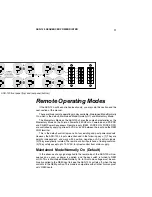
The barrier terminal strip on the ASD-120 rear panel allows a switch (or switches)
to be connected to turn the unit on and off at a distance, and provides various
power, status and relay closure outputs. In the most basic configuration, only two
Class 2 wires and an SPST switch are needed to initiate an on or off sequence. The
switch may be either a momentary or maintained-contact type. An LED may also
be installed at the remote end to indicate power is on, but will require a third wire.
Momentary vs. Maintained Contact Switching
An on-off switch of either kind may be used to actuate the ASD-120’s remote
operation. Maintained switches, such as most toggle switches and push-on/push-
off button switches, and including the Furman RS-1 wall mount key lock switch, are
open until actuated, then stay closed until actuated again. Momentary switches,


