ASD-120 SEQUENCED POWER DISTRO
7
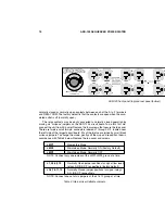
ASD-120 Buss Bar Block
the insulation of the individual conductors. When stripping the individual conduc-
tors, be careful not to cut through any of the copper strands. All of the individual
conductors should be stripped one-half inch. Please see table below for individual
wire lengths.
For 3 phase wiring, the following conductors are needed: Ground = Green or
Green with Yellow Stripe. X, Y, Z phases: There is no standard that matches colors
to letters, but X = Black, Y = Red, and Z = Blue can be used as a reference. W=
Neutral and is always white. For 240V Single phase, Ground = Green or Green with
Yellow Stripe, X = Black (hot), Y = Red (hot), W = White (neutral). 120V/120A
service is not expected to be used much, if at all, with this product, however, Ground,
X, and W are used just as in 240V Single phase.
After threading the cable end through the strain relief clamp, connect the stripped
conductors to the buss bar block. Be sure to put each wire in the lower part of its
terminal, so that it is compressed above and below by copper rather than by the set
screw itself. Tighten the set screws securely.
4. Divide the load: Since there is more than one hot wire, the six 20 amp loads
must be split among them and balanced as well as possible. This is done by recon-
necting the wires from the buss bars to the six circuits. There are two wires to each
circuit, a hot (black) and a neutral (white). Only the black wires may be moved. All
white wires must connect to the NEU (neutral) buss bar.
Each black wire is labeled with a letter (A, B, C, D, E, or F) corresponding to the
circuit it goes to. The connections are made by Fast-On terminals on the buss bars.
Table 2, Suggested Cable Strip Lengths
Color of Wire
Wire End Stripped
Total Length of Wire
WHITE (NEU)
.5 inch
6.0 inches
BLUE (Z)
.5 inch
5.0 inches
RED (Y)
.5 inch
4.0 inches
BLACK (X)
.5 inch
4.0 inches
GREEN (Ground)
.5 inch
4.0 inches


