


7
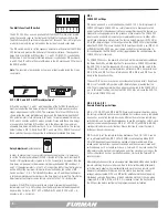
Start Sequence Button Switch
The Start Sequence button located on the left side of the front
panel can be used for sequencing power up or power down.
The “START SEQUENCE” button is only activated when the key
switch is set to the “Remote” mode. The function of this switch
depends on the position of DIP Switch 7 and the duration of time
that the button is depressed. Please note, setting the key switch
to ON defeats operation of the START SEQUENCE push button.
Both the key switch and the START SEQUENCE button operate in
either Maintained or Momentary mode.
START
SEQUENCE
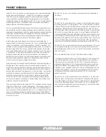
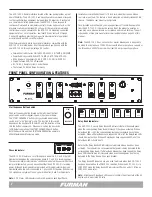
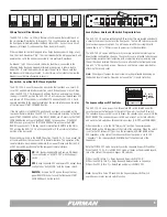
FRONT PANEL CONFIGURATION & FEATURES
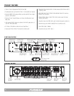
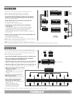
Other Furman products which have remote interfaces compatible with the
ASD-120 2.0 are listed below. All of these products can be used with the
new ASD-120 2.0 through low voltage DC control.
• Furman Contractor Series CN-1800S, CN-2400S, CN-15MP & CN-20MP
• PowerPort & Legacy MiniPorts MP-15, MP-20, MP-15Q & MP-20Q
• M-8S & Legacy Sequencers PS-8R, PS-PRO, PS-8R II & PS-PRO II
• Original Furman ASD-120 & Powerlink
• RS-1 & RS-2 Remote System Control Panels
• The Furman PS-REL AC Relay Accessory
Note:
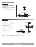
The ASD-120 2.0 has no line cord or master breaker, and is designed to
be wired to a single phase 120/240V source with 60 amps per phase capacity, or
to a three phase 208 WYE source with at least 40 amps capacity per phase.
PHASE
X Y Z
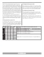
Phase Indicators:
The ASD-120 2.0 features a set of three phase indicators; X, Y, and Z that will
illuminate green when the corresponding phase (X, Y, and Z) is receiving power.
These are sometimes referred to as “confidence indicators” because when these
lamps are illuminated, you can be confident that the ASD-120 2.0 is receiving
power. Although three indicators are provided, all three indicators will only be
illuminated when the unit is connected to 3-phase 208-WYE power. When using
240 split phase, only two of the only phase indicators (X and Y) will illuminate
Note:
X Y Z Status LED indicators confirm AC power on each Input Phase.
Delay Bank Indicators:
The ASD-120 2.0 has six Delay Bank LED indicators that will illuminate green
when the corresponding Delay Bank (A through F) has been activated. When a
Delay Bank LED is OFF, the corresponding rear panel receptacle has not been
activated. When all Delay Banks have sequenced ON, all of the Delay Bank LEDs
should illuminate green. When all Delay Banks have sequenced OFF, all of the
Delay Bank LEDs should be off.
Note that the Delay Bank LED indicators only indicate when a bank has been
activated. The indicators do not guarantee that power is being delivered to the
corresponding Delay Bank. If a Delay Bank breaker has been tripped, the Delay
Bank LED indicator may still illuminate green even though power is not being
delivered to the Delay Bank with an open breaker.
The Delay Bank LED indicators are also used to indicate when the ASD-120 2.0
has been disabled due to a FORCE OFF condition. When the ASD-120 2.0 is in
FORCE OFF mode the Delay Bank LED indicators will flash on and off. More on
FORCE OFF mode later…
Note:
A front panel Delay Bank LED indicator confirms the active state of the AC
duplex and its associated DC relay.
START
SEQUENCE
REMOTE
DLY
ADJ
DELAY A DELAY B
DELAY C
PHASE
X Y Z
DELAY D DELAY E
DELAY F
OFF ON
1 2 3 4 5 6 7
ASD-120 2.0
120 AMP POWER SEQUENCER
(SEE COVER PLATE)
ALWAYS ON
ALWAYS OFF
S
E
Q
START
SEQUENCE
REMOTE
DLY
ADJ
DELAY A DELAY B
DELAY C
PHASE
X Y Z
DELAY D DELAY E
DELAY F
OFF ON
1 2 3 4 5 6 7
ASD-120 2.0
120 AMP POWER SEQUENCER
(SEE COVER PLATE)
ALWAYS ON
ALWAYS OFF
S
E
Q
START
SEQUENCE
REMOTE
DLY
ADJ
DELAY A DELAY B
DELAY C
PHASE
X Y Z
DELAY D DELAY E
DELAY F
OFF ON
1 2 3 4 5 6 7
ASD-120 2.0
120 AMP POWER SEQUENCER
(SEE COVER PLATE)
ALWAYS ON
ALWAYS OFF
S
E
Q
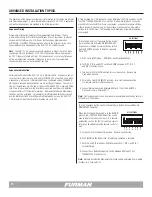
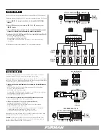
The ASD-120 2.0 Remote interface located at the rear panel provides a great
deal of flexibility. The ASD-120 2.0 can be configured to command or respond
to other controller-type equipment via low voltage DC impulses. If configured
as a remotely controlled power source, the ASD-120 2.0 can respond to
continuous maintained or momentary contact closures, open contacts, or the
presence or absence of external DC voltage. At the same time, maintained
control signals can be generated by the ASD-120 2.0 triggering connected
equipment into or out of operation. Low level DC relay contacts A through
F on each Delay Bank provide the means for external control of equipment
associated with each AC circuit Delay Bank.
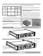
Installation is simplified by the unit’s 19 inch rack-mount design and hidden
rear rack-mount ears. This feature is found alongside an industry standard 2RU
chassis. The hidden rear mounts are adjustable.
Once installed and configured, you may expect years of trouble-free operation
from the ASD-120 2.0. If during the service life of the product a question or
issue may arise, please welcome our assistance and contact Furman. The unit
is backed by a three year manufacturer’s warranty detailed on page 22 of this
manual.


