


14
3
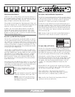
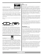
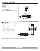
. Control by Remote Contact Closure (Remote Activation MAINTAINED OFF) Any
external dry switch CONTACT CLOSURE can be used to activate the sequence ON.
An Open Contact will result in a sequence OFF.
A. Turn Key Switch to the REMOTE position – Remove key if desired.
B. DIP 6 is in the up position - GND ON mode.
C. DIP 7 in the down position - MNT (Maintained) operation is now
selected.
D. Set Multi-Function DIP 5 DOWN reserving DIP 1, DIP 2, and DIP 3 for delay
timing.
E. Connected external contacts between the REM and GND connections at the
REMOTE 4-Pin Connector.
Note:
The Front Panel Start Sequence Button is disabled when DIP 6 is in the
GND ON mode (UP).
4
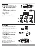
. SEQUENCE ON using external 5 to 30VDC power supply. In this mode, an
external power supply will cause the ASD-120 2.0 to sequence ON. When the
power supply is removed, the ASD-120 2.0 will automatically sequence OFF.
A. Turn Key Switch to the REMOTE position – Remove key if desired.
B. DIP 5 in the up position.
C. DIP 6 is in the down position.
D. DIP 7 in the down position - MNT (Maintained) operation is now
selected.
E. Reserve DIP 1, DIP 2, and DIP 3 for delay timing.
F. Connected external DC supply (+) to REM pin and (-) to GND pin at the
REMOTE 4-Pin Connector.
Note:
The Front Panel Start Sequence Button is disabled when DIP 6 is in the
GND ON mode (UP).
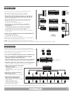
5.
SEQUENCE OFF using external 5 to 30VDC power supply. In this mode an
external power supply will prevent the ASD-120 2.0 from sequencing ON. The
ASD-120 2.0 will automatically sequence ON when the DC power is removed.
A. Turn Key Switch to the REMOTE position – Remove key if desired.
B. DIP 5 in the down position - 12V OFF mode.
C. DIP 6 is in the down position.
D. DIP 7 in the down position - MNT (Maintained) operation is now
selected.
E. Reserve DIP 1, DIP 2, and DIP 3 for delay timing.
F. Connected external DC supply (+) to REM pin and (-) to GND pin at
the REMOTE 4-Pin Connector will cause the unit to SEQUENCE OFF.
Note:
The ASD-120 2.0 is disabled when DIP 4 is set for (N.C.) mode. Factory
DIP 4 (N.O.) mode is recommended. Only a short across the Forced Off terminals
will activate the ASD-120 2.0 when DIP 4 is in (N.C.) mode. This DIP setting is
reserved for alarm systems. Factory default for DIP 4 is (N.O) mode position UP.
Note:
The Front Panel Start Sequence Button is disabled when DIP 6 is in GND
ON mode (Position UP).
Note:
When programming a new configuration it is recommended to start with
the front panel Key Switch in the OFF position.
Note:
Loss of AC Power or utility interruption in Maintained Mode will result in all
Banks returning to the previous state when the utility service is restored. Main-
tained On, Banks will return to ON. Maintained OFF, Banks will return to OFF.
Note:
Loss of AC Power or utility interruption in Momentary Mode will result in all
Banks returning to an OFF state when the utility service is restored.


