


13
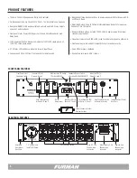
ADVANCED INSTALLATION TOPICS
The beginning of the manual provides basic information for those who are familiar
with Furman equipment. A more complete description of ASD-120 2.0 operations
and configuration options are provided in the following sections.
Sequence Timing
Please note all Banks participate in the programmed time interval. The pro-
grammed delay time will cycle through all Banks A thru F, regardless of a Bank’s
assignment on the Bypass Switch. Banks that have been programmed as
ALWAYS ON, or ALWAYS OFF experience no effect in the program timing, since
bypassed Banks are independent of the ASD-120 2.0 control circuitry.
Note:
The ASD-120 2.0 sequences each Delay Bank in order from A to F when
sequencing ON, and turn Banks F to A OFF in the reverse order when sequenc-
ing OFF. Triggers to initiate an ON or OFF sequence can occur at any time even
during a programmed sequence. If triggered to do so, a unit’s programmed
sequence will be and can be reversed at any time.
Sequence Initialization
Factory default mode for the ASD-120 2.0 is Maintained On. A sequence can oc-
cur at any time, reverse at any time, and/or FORCED OFF at any time, even while
a sequence is in progress. If Maintained Mode is configured and an SEQUENCE
ON trigger is received while the Banks are On, nothing will happen. The same is
true if all Delay Banks are OFF and a trigger to SEQUENCE OFF is received. There-
fore if two or more remote switch locations are desired and the user would like
to sequence ON or OFF from both locations. Momentary Mode and Momentary
Switches must be employed. For example, if two Maintained switches are used
and the Multi-Function Set is configured in Maintained On mode, the ASD-120
2.0 will remain ON until both remote locations are set to OFF.
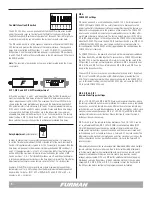
A time-delayed On or Off sequence can be initiated at the front panel Key Switch,
the START SEQUENCE button, or using the 4-Pin Remote Interface. The config-
uration Multi-Function DIP switches can program a sequence response utilizing
either Closed or Open Contacts, or the presence or absence of an external DC
voltage (5 to 30VDC max). The following basic examples of remote integration
are provided:
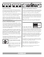
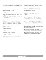
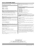
ON
DIP SETTINGS
1 2 3 4 5 6 7
ON
DIP SETTINGS
1 2 3 4 5 6 7
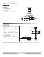
1.
Key Switch and Start Sequence Button Control
(Local and Remote Activation MAINTAINED ON).
A sequence is initiated by turning the key switch
past the REMOTE position to initiate a sequence
ON or OFF.
A. DIP 7 set to (MNT) mode – DOWN Position Maintained Mode.
B. Set DIP 5, DIP 6, and DIP 7 switches DOWN reserving DIP 1, DIP 2,
and DIP 3 for delay timing.
C. Turn Key Switch to the ON position for Local operation – Remove key
if and when desired.
D. Or turn Key Switch to REMOTE position – Use Start Sequence button
or a remote switch to initiate sequence.
E. Connect Maintained switch between REM and 12V at the REMOTE 4
Pin Connector (e.g. Furman RS-1).
Note:
Start Sequence button on front panel is inoperative when the key switch is
in the ON or OFF positions.
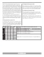
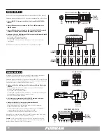
2.
Start Sequence Button Control or Remote Push Button (Local and Remote
MOMENTARY Operation)
When the front panel Key Switch is in the REMOTE
position, the START SEQUENCING buttons can be
used to toggle the sequence On or Off. A remote
pushbutton such as the RS-2 momentary contact
switch can be added to provide remote control as
well:
A. Set Key Switch to the Remote position - Remove key if desired.
B. DIP 7 (MOM) in the UP position - Momentary operation is selected.
C. Set DIP 5 and DIP 6 switches DOWN reserving DIP 1, DIP 2, and DIP 3
for delay timing.
D. Connect Push Button Momentary Switch between REM and 12V at
the REMOTE 4 Pin Connector.
Note:
Multiple Push Button Momentary Switches can be employed from multiple
locations (e.g. Furman RS-2).


