With Soldering Iron:
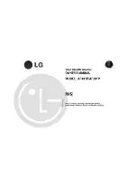
(1) Using desoldering braid, remove the solder from all
pins of the flat pack-IC. When you use solder flux
which is applied to all pins of the flat pack-IC, you
can remove it easily. (Fig. S-1-3)
(2) Lift each lead of the flat pack-IC upward one by one,
using a sharp pin or wire to which solder will not
adhere (iron wire). When heating the pins, use a fine
tip soldering iron or a hot air desoldering machine.
(Fig. S-1-4)
(3) Bottom of the flat pack-IC is fixed with glue to the
CBA; when removing entire flat pack-IC, first apply
soldering iron to center of the flat pack-IC and heat
up. Then remove (glue will be melted). (Fig. S-1-6)
(4) Release the flat pack-IC from the CBA using tweez-
ers. (Fig. S-1-6)
With Iron Wire:
(1) Using desoldering braid, remove the solder from all
pins of the flat pack-IC. When you use solder flux
which is applied to all pins of the flat pack-IC, you
can remove it easily. (Fig. S-1-3)
(2) Affix the wire to a workbench or solid mounting point,
as shown in Fig. S-1-5.
(3) While heating the pins using a fine tip soldering iron
or hot air blower, pull up the wire as the solder melts
so as to lift the IC leads from the CBA contact pads
as shown in Fig. S-1-5.
(4) Bottom of the flat pack-IC is fixed with glue to the
CBA; when removing entire flat pack-IC, first apply
soldering iron to center of the flat pack-IC and heat
up. Then remove (glue will be melted). (Fig. S-1-6)
(5) Release the flat pack-IC from the CBA using tweez-
ers. (Fig. S-1-6)
Note:
When using a soldering iron, care must be taken to
ensure that the flat pack-IC is not being held by glue.
When the flat pack-IC is removed from the CBA,
handle it gently because it may be damaged if force
is applied.
Flat Pack-IC
Desoldering Braid
Soldering Iron
Fig. S-1-3
Fine Tip
Soldering Iron
Sharp
Pin
To Solid
Mounting Point
Soldering Iron
Iron Wire
or
Hot Air Blower
Fig. S-1-4
Fig. S-1-5
Fine Tip
Soldeing Iron
CBA
Flat Pack-IC
Tweezers
Fig. S-1-6
1-3-2
NOTE_1
Summary of Contents for 23C-250
Page 22: ...1 8 3 1 8 4 1 8 5 H8624SCM1 Main 1 4 Schematic Diagram...
Page 23: ...1 8 6 1 8 7 1 8 8 H8624SCM2 Main 2 4 Schematic Diagram...
Page 24: ...1 8 9 1 8 10 1 8 11 H8624SCM3 Main 3 4 Schematic Diagram...
Page 25: ...1 8 12 1 8 13 1 8 14 H8624SCM4 Main 4 4 Schematic Diagram Function Schematic Diagram H8743SCF...
Page 26: ...1 8 15 1 8 16 Jack Schematic Diagram H8622SCJ...
Page 27: ...1 8 17 1 8 18 SECAM Schematic Diagram H8624SCS...
Page 30: ...1 8 26 1 8 25 BH8700F01031 Function CBA Top View Function CBA Bottom View...
Page 31: ...1 8 28 1 8 27 BH8700F01021 Jack CBA Top View Jack CBA Bottom View...
Page 32: ...1 8 30 1 8 29 SECAM CBA Top View SECAM CBA Bottom View BH8700F01011 C...
Page 58: ...EXPLODED VIEWS Front Panel A1X 3 1 1 H8743FEX...
Page 60: ...Packing Some Ref Numbers are not in sequence S2 S2 X4 S1 X1 X2 X20 X3 Unit S3 3 1 3 H8740PEX...
Page 78: ...23C 250 23C 250A H8743FP Printed in Japan 2001 04 20 HO...