


5-4
SPARC Enterprise M4000/M5000 Servers Service Manual • December 2010
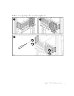
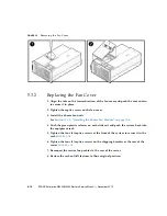
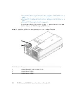
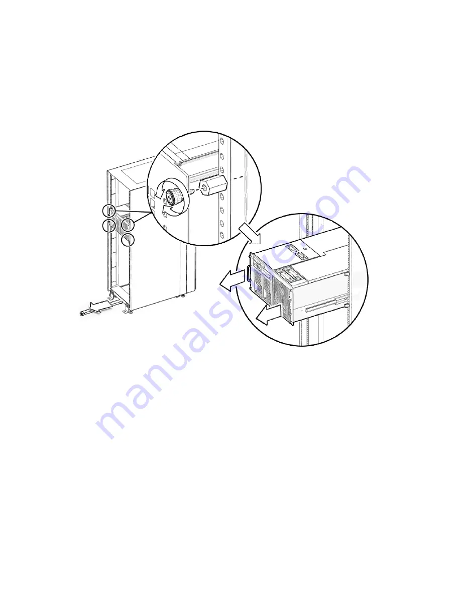
3. Loosen the four (4) captive screws at the front of the server (
FIGURE 5-2
Loosening the Captive Screws and Pulling Out the Server
4. Pull the system to the fan stop.
The system automatically locks in place at the fan stop.
5.1.2
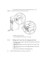
Sliding the Server Into the Equipment Rack
1. Push the green plastic releases on each slide rail and push the server back into
the equipment rack.
2. Tighten the four (4) captive screws at the front of the server to secure it in the
rack (
3. Tighten the four (4) captive screws on the shipping brackets at the rear of the
server (
4. Restore the rack antitilt features to their original position.
Summary of Contents for SPARC Enterprise M4000
Page 4: ......
Page 62: ...2 38 SPARC Enterprise M4000 M5000 Servers Service Manual December 2010 ...
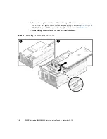
Page 89: ...Chapter 5 Internal Components Access 5 7 FIGURE 5 4 Removing the M5000 Server Top Cover ...
Page 126: ...6 34 SPARC Enterprise M4000 M5000 Servers Service Manual December 2010 ...
Page 132: ...7 6 SPARC Enterprise M4000 M5000 Servers Service Manual December 2010 ...
Page 158: ...8 26 SPARC Enterprise M4000 M5000 Servers Service Manual December 2010 ...
Page 245: ...Chapter 14 Backplane Unit Replacement 14 11 FIGURE 14 4 Removing the M5000 Server Backplane ...
Page 248: ...14 14 SPARC Enterprise M4000 M5000 Servers Service Manual December 2010 ...
Page 256: ...15 8 SPARC Enterprise M4000 M5000 Servers Service Manual December 2010 ...
Page 288: ...E 6 SPARC Enterprise M4000 M5000 Servers Service Manual December 2010 ...
Page 304: ...F 16 SPARC Enterprise M4000 M5000 Servers Service Manual December 2010 ...
Page 308: ...G 4 SPARC Enterprise M4000 M5000 Servers Service Manual December 2010 ...


