


2-18
SPARC Enterprise M4000/M5000 Servers Service Manual • December 2010
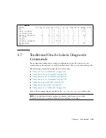
2.5
LED Functions
LED lights help the user find the component and provide information on the state of
the component.
This section explains the LEDs of each component that are to be checked when a
component is replaced. Most components are equipped with LEDs that help indicate
which component has the error and an LED to indicate whether the component can
be removed.
Some components, such as DIMMs, do not have LEDs. The state of a component
without LEDs can be checked using the
showhardconf
and
ioxadm
XSCF Shell
commands from the maintenance terminal. See the
SPARC Enterprise
M3000/M4000/M5000/M8000/M9000 Servers XSCF User’s Guide
for more detailed
information.
describes the LEDs and their functions.
TABLE 2-10
Component LEDs
LED Name
Display and Meaning
READY (green)
Indicates whether the component is operating.
On
Indicates that the component is operating. The component
cannot be disconnected and removed from the server while
the READY LED is On.
Blinking
Indicates that the component is being configured (or
disconnected).
For an XSCF unit it indicates that it is being initialized.
Off
Indicates that the component is stopped. The component can
be disconnected and replaced.
CHECK
(amber)
Indicates that the component contains an error or that the component is a
target for replacement.
On
Indicates that an error has been detected.
Blinking
Indicates that the component is ready to be replaced. The
blinking LED acts as a locator.
Off
Indicates no known error exists.
Summary of Contents for SPARC Enterprise M4000
Page 4: ......
Page 62: ...2 38 SPARC Enterprise M4000 M5000 Servers Service Manual December 2010 ...
Page 89: ...Chapter 5 Internal Components Access 5 7 FIGURE 5 4 Removing the M5000 Server Top Cover ...
Page 126: ...6 34 SPARC Enterprise M4000 M5000 Servers Service Manual December 2010 ...
Page 132: ...7 6 SPARC Enterprise M4000 M5000 Servers Service Manual December 2010 ...
Page 158: ...8 26 SPARC Enterprise M4000 M5000 Servers Service Manual December 2010 ...
Page 245: ...Chapter 14 Backplane Unit Replacement 14 11 FIGURE 14 4 Removing the M5000 Server Backplane ...
Page 248: ...14 14 SPARC Enterprise M4000 M5000 Servers Service Manual December 2010 ...
Page 256: ...15 8 SPARC Enterprise M4000 M5000 Servers Service Manual December 2010 ...
Page 288: ...E 6 SPARC Enterprise M4000 M5000 Servers Service Manual December 2010 ...
Page 304: ...F 16 SPARC Enterprise M4000 M5000 Servers Service Manual December 2010 ...
Page 308: ...G 4 SPARC Enterprise M4000 M5000 Servers Service Manual December 2010 ...


