


33
Appendix A Differences between the Emulation Pod and a Regular Production MCU
■
Pins to which a Buffer Circuit is Added
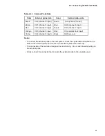
Table A-1 shows the pins to which a buffer circuit is added.
The pin names listed in the table are the pin names of the evaluation MCU.
For the relationship to the actual MCU, contact the Fujitsu sales division.
Table A-1
Pins to which a Buffer Circuit is Added
Evaluation MCU pin name
Evaluation MCU pin name
P00
P10
P01
P11
P02
P12
P03
P13
P04
P14
P05
P15
P06
P16
P07
P17
Summary of Contents for MB2145-507
Page 9: ...viii ...
Page 13: ...xii ...
Page 27: ...14 CHAPTER 1 PRODUCT HANDLING AND SPECIFICATIONS ...
Page 31: ...18 CHAPTER 2 CONNECTION AND SETTINGS Figure 2 2 1 Connecting the 2140 Main Unit ...
Page 43: ...30 CHAPTER 2 CONNECTION AND SETTINGS ...
Page 47: ...34 APPENDIX ...
Page 49: ......


