


C141-E134-01EN
5 - 21
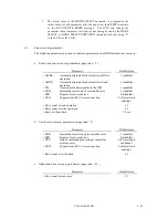
(3)
Caching parameters
The following parameters are used to optimize IDD Read-Ahead caching operations under the
system environments. Refer to Chapter 2 of SCSI Logical Interface Specifications for further
details.
Parameter
Default value
• IC:
Initiator control
0 (Drive-specific
control (page
cache))
• RCD:
Disabling Read-Ahead caching operations
0 (enabled)
• WCE:
Write Cache Enable
1 (enabled)
• MS:
Specifying the multipliers of "minimum
prefetch" and "maximum prefetch" parameters
0 (Specifying
absolute value)
• DISC:
Prefetch operation after track switching during
prefetching
1 (inhibit)
• Number of blocks for which prefetch is suppressed
X'FFFF'
• Minimum prefetch
X'0000'
• Maximum prefetch
X' XXXX'
(1 cache segment)
• Number of blocks with maximum prefetch restrictions
X'FFFF'
• Number of segments
X'08'
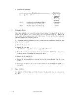
Notes:
1.
When Read-Ahead caching operations are disabled by the caching parameter, these
parameter settings have no meaning except write cache feature.
2.
Determine the parameters in consideration of how the system accesses the disk. When the
access form is not determined uniquely because of the processing method, the parameters
can be re-set actively.
3.
For sequential access, the effective access rate can be increased by enabling Read-Ahead
caching operations and Write Cache feature.
(4)
Control mode parameters
The following parameters are used to control the tagged queuing and error logging.
Summary of Contents for MAM3184MC
Page 1: ...C141 E134 01EN MAM3367MC MP SERIES MAM3184MC MP SERIES DISK DRIVES PRODUCT MAINTENANCE MANUAL ...
Page 18: ...This page is intentionally left blank ...
Page 28: ...This page is intentionally left blank ...
Page 36: ...This page is intentionally left blank ...
Page 66: ...C141 E134 01EN 4 14 Figure 4 17 External operator panel connector CN2 ...
Page 124: ...8 8 C141 E134 01EN Figure 8 3 Block diagram of read write circuit ...
Page 130: ...This page is intentionally left blank ...
Page 134: ...This page is intentionally left blank ...
Page 140: ...This page is intentionally left blank ...
Page 148: ...This page is intentionally left blank ...
Page 150: ...This page is intentionally left blank ...
Page 151: ......
Page 152: ......


