background image

U41224-J-Z916-1-76

 39

6

Configuration

In order to be able to configure the system, the LAN Console must have been 
connected to the RCA via a LAN and the RCA must have been connected to 
one or more RM or PRIMEPOWER (MR) servers via V.24 cabling (see figure 
“Connections on the rear of the device” on page 29).

From the LAN Console, the system administrator manages both the RCA and 
the console connections of the attached RM and PRIMEPOWER (MR) servers.

No further preparatory steps are required for RM systems but PRIMEPOWER 
(MR) servers have to be configured as described in the following sections.

6.1

Configuring the PRIMEPOWER (MR)

If you have connected your LAN Console to a PRIMEPOWER (MR) instead of 
a graphical console - including keyboard and mouse - you have to redirect all 
console inputs and outputs to serial port A. The console comes with an adapter 
already in place (25-pin --> 9-pin).

To do this, you first connect


port A by means of a V.24 cable to the required port 

on the RCA in accordance with the description in the sections “Connecting the 
cables” on page 29 and “Cable types” on page 34 and the definition given in 
“Commands” on page 43, section 

mklancon

.

The Solaris operating system detects which serial port is connected, i.e. no 
explicit reconfiguration is required.

The terminal type needs to be set for the console login:

Ê

In the 

/etc/inittab

 file, set the terminal type 

xterm 

in the entry for the console 

login:

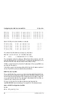
...:/usr/lib/saf/ttymon -g ... -d /dev/console -T xterm

-l console

The line speed for the connected port of the RCA must be set to 9600 baud in 
the RCA setup routine, see section “Ports“ in the Appendix.

Summary of Contents for LAN Console

Page 1: ... Configuration and Operation E Hübner Hatzel Fujitsu Siemens Computers GmbH UNIX 33094 Paderborn e mail Internet DOCetc pdb siemens de Tel 05251 814895 Fax 0 52 51 8 1 52 48 U41224 J Z916 1 76 Sprachen De Edition October 2001 ...

Page 2: ...your comments are included at the back of the manual There you will also find the addresses of the relevant User Documentation Department Copyright and Trademarks Copyright 2000 2001 Fujitsu Siemens Computers GmbH All rights reserved Delivery subject to availability right of technical modifications reserved All hardware and software names used are trademarks of their respective manufacturers This ...

Page 3: ...N Console 15 4 3 Overview of connections 16 4 3 1 Connecting the keyboard 17 4 3 2 Connecting the mouse 17 4 3 3 Connecting devices with a serial or parallel interface 18 4 3 4 Connecting the monitor 18 4 3 5 Connecting the LAN Console to the power supply 19 4 4 Operating the LAN Console 21 4 4 1 Switching on off the LAN Console 21 4 4 1 1 System unit is switched off 21 4 4 1 2 System unit is read...

Page 4: ...ing the LAN Console and RCA 40 6 2 1 Initial configuration of the LAN Console and RCA 42 6 2 1 1 Configuring the LAN Console 43 6 2 1 2 Configuring the RCA 45 6 2 2 New ports for the RCA 51 6 2 3 Another RCA connected to the LAN Console 52 6 2 4 Another LAN Console connected to the RCA 52 6 2 5 Modifying the LAN Console and RCA 52 6 2 5 1 Modifying the configuration entry for an RCA port 53 6 2 5 ...

Page 5: ...e rtty monitor 84 7 3 3 Configuration entries for the LAN Console 84 7 3 4 System information for the RCA 85 7 4 Error situations 86 7 4 1 No response from the RCA 86 7 4 2 Failure to establish a connection 86 7 4 3 Disrupted RCA LAN Console connection 87 7 4 3 1 LAN connection disrupted 87 7 4 3 2 No output in console window 88 7 4 4 Invalid password for RCA setup 88 7 4 5 Incorrect remote call o...

Page 6: ...U41224 J Z916 1 76 Contents Glossary 109 Abbreviations 111 Related publications 115 Index 125 ...

Page 7: ...m console for midrange servers and as a system management console for enterprise serv ers Midrange Server This includes the RM 300 400 600 ServerNode models and the PRIMEPOWER midrange server models 100N 200 400 600 Genuine LAN console software is used on the LAN Console for managing the server systems The Remote Communication Adapter RCA can be used as a V 24 Ethernet converter Enterprise Server ...

Page 8: ...nnection for all networked RM or PRIMEPOWER MR serv ers is also handled via the LAN Console Teleservice gateway so only one line to the Service organization is needed for all networked RM or PRIMEPOWER MR servers When connected to a LAN local area network the console can be located at any point in the LAN for example in another room or building The distance is no longer restricted to 15 m max The ...

Page 9: ... device This manual describes how to install the LAN Console and the RCA how to con figure the system and how to operate the LAN Console The chapter LAN Console on page 9 tells you everything about installing the LAN Console and setting up the software from the CD ROM The chapter Installing the RCA on page 29 presents the hardware of the RCA It tells you how to install the device cable it and star...

Page 10: ... liquid crystal dis play Bold monospace font This indicates user inputs in examples Italics This indicates commands file names menu names and inputs in continuous text Bold This indicates emphasis in the text Taste This indicates keys or key combinations in continu ous text I This indicates additional information and tips V Title This indicates information which if not heeded may jeopardize your h...

Page 11: ...otice is for USA users only This equipment has been tested and found to comply with the limits for a Class B digital device pursuant to Part 15 of the FCC Rules These limits are designed to provide reasonable protection against harmful interference V Safety notes Only transport the device in its original packaging or in other suitable packaging which will protect it against impact and jolts Conden...

Page 12: ... damaging them When connecting the device note the information given in the section Connecting the cables on page 29 Do not connect or disconnect communication cables during a thun derstorm Make sure that no liquids penetrate the interior of the device risk of electric shock short circuit In cases of emergency e g damage to the housing controls or power cable or penetration of liquid turn the devi...

Page 13: ...rd Debug Monitor or OBP Open Boot Prom Monitor and rebooting of a system can be carried out with the LAN Console 5 The xscon tool is used to select and represent one or more consoles of RM and PRIMEPOWER MR servers 6 RM and PRIMEPOWER MR servers can also be booted and installed remotely via LAN 7 Connection to Teleservice 8 The LAN Console can be used simultaneously as a console on RM and PRIMEPOW...

Page 14: ...y 10 The console can also be used as a computer system in its own right 3 2 Architecture Figure 1 Architecture of the LAN Console RM systems and or PRIMEPOWER MR systems 2 x V 24 4 x V 24 Remote Communication Adapter RCA Ethernet TCP IP LAN Console ...

Page 15: ...via the LAN TCP IP The LAN Console can be used as a standalone system in desktop housing with a desktop monitor standard PC keyboard German International and 3 button mouse Figure 2 LAN Console as a standalone system A mounting frame is provided for installing the LAN Console in a 19 inch rack 3 5 height units as well as a pull out rack console with fold away TFT monitor 15 35cm and keyboard with ...

Page 16: ...le Figure 4 Fold away monitor of LAN Console in the rack The power supply is enabled when the monitor is tilted open At the same time a safety mechanism on the right hand side of the rack module prevents the rack being pushed back in while the monitor is tilted open ...

Page 17: ...VD drive 12x DVD 40x CD ROM or better Diskette drive 1 44 MByte 2 x Fast Ethernet onboard 2 x 10 100 Mbits s Hard disk 2 x 20 GByte V 24 interface COM1 and COM2 DB9 Connector COM2 for Teleservice PS 2 interface 3 button mouse for X Windows interface PS 2 interface Keyboard German international Audio on board Table 1 LAN Console hardware components Upgrade to SMC DAT drive DDS 4 Main memory extensi...

Page 18: ...ou will find details of this in the English language Operating Manual for the RM600 and PRIMEPOWER MR as well as in the general safety notes for RM SR 2000 and GP7000F PRIMEPOWER MR servers Mains voltage range switchable 100V 125V 200V 240V Rated frequency 50 60 Hz Power consumption approx 60 W Power factor cosϕ 120V 0 90 230V 0 75 Table 3 Power ratings ...

Page 19: ...C Height above sea level m 25 60 15 98 3000 Physically active substances operation 3M2 Physical environmental conditions Operation Transport 3M2 2M2 Required space for service activities Minimum distance mm front rear 1000 1000 Table 4 Environmental conditions Dimensions and weight Desktop housing Rack module Breadth mm Depth mm Height mm Weight basic configuration kg 1 Weight SMC kg 1 1 without d...

Page 20: ...f the scope of delivery and have to be ordered separately 4 2 2 Unpacking and checking the delivery unit You should keep the original device packaging in case the device has to be transported Ê Unpack all the parts Ê Check the package contents for visible transport damage Ê Check that the delivery matches the details on the delivery note If you discover transport damage or inconsistencies between ...

Page 21: ...conditions on page 13 It should be pro tected from dust humidity and heat The must be at least 200 mm free space to the front and rear of the sys tem unit so that the unit is adequately ventilated The fan areas on the monitor and system unit should not be covered Do not place any objects over 40 kg in weight on the system unit and do not stack several system units above one another We recommend yo...

Page 22: ...e 6 Connections on the rear of the LAN Console V Warning The power plug must be pulled out AX1105 motherboard USB1 Serial port A Ethernet 1 connector Ethernet 0 connector Line out J2 Line in J3 Microphone in J4 Video connector J5 Headphone out J1 Serial port B USB0 PCI slots on the motherboard PCI slot cover plate slot 4 2 J24 1 J25 3 J23 PS 2 connector mouse PS 2 connector keyboard ...

Page 23: ...e connected devices see documentation for the connected device and for the operating system 4 3 1 Connecting the keyboard The keyboard is not part of the scope of delivery and has to be ordered sepa rately I Only use the keyboard cable supplied Ê Insert the round plug of the keyboard cable into the keyboard port on the system unit Ê Insert the other plug for the keyboard cable into the socket on t...

Page 24: ...red driver is not on the hard disk you have to install it from the diskette or CD which was supplied with the device or with the application program 4 3 4 Connecting the monitor The monitor is not part of the scope of delivery and has to be ordered sepa rately Ê Prepare the monitor as described in the Operating Manual for the monitor Ê Insert the data cable for the monitor into the monitor port on...

Page 25: ...nitor socket on the system unit from the mains A monitor connected to the monitor socket must always be discon nected using its own ON OFF button 4 3 5 Connecting the LAN Console to the power supply Ê Check the power supply setting V Warning The value displayed or indicated with the arrow must conform with the local power supply Changing the power supply when it is set incorrectly I Your LAN Conso...

Page 26: ...onsole Figure 9 Setting the power supply 1 groove for inserting the screwdriver Figure 10 Connector on system unit Ê Connect the power cable for the system unit to the system unit 1 and then to the earthed power outlet 2 100 V 125 V 200 V 240 V 1 1 2 1 ...

Page 27: ...in switch 1 is in position O the power LED 3 is not lighting and the ON OFF button 2 is not functional 4 4 1 2 System unit is ready to operate The main switch 1 is in position I and the power LED 3 is lighting orange You can enable the system unit in this mode with the ON OFF button 2 The ready to operate state corresponds to the stand by status on a television The power LED 3 is described in grea...

Page 28: ...he power LED is lighting green the system unit is switched on 2 Hard disk indicator The indicator lights when the hard disk drive of the system unit is accessed 3 Message indicator This indicator is intended for future applications 4 DVD ROM indicator The indicator lights when the DVD ROM drive of the system unit is accessed The CD must not be removed under any circumstances while the indicator is...

Page 29: ...Solaris manual use the arrangement proposed here instead This will save you repartitioning when using the LAN Console as an SMC Component Pre installation Operating system Solaris 8 Entire distribution plus OEM Sup port 64 bit incl Disksuite SUNVTS Teleservice V4 0 Language German English is automatically installed as well Table 7 Pre installation of the LAN Console Partition Directory Hard disk p...

Page 30: ...e network time zone and root password are required Language setting When the Solaris operating system has booted a mask appears prompting the user name The desired language can be chosen in the following menu Desktop Login Options Languages Once you have entered the password the CDE Common Desktop Environ ment is started All other parameters are set using the usual Solaris tools ...

Page 31: ...lement CD is required The LAN Console software is stored on the Control CD System manage ment CD The Control CD contains the following packages for the LAN Con sole Installation procedure Ê Insert the Control CD The required packages are installed using the Web start wizard The File Manager window opens automatically and shows the contents of the CD ROM Figure 13 File Manager window for the Contro...

Page 32: ...ins SMAWtelx SMAWxsco Where there are several systems to be administered by the LAN Console at the same time in one or more domains the licensed Domain Admin 2 0 product must be installed see manual WebSysAdmin Domain Admin 2 0 Ê Teleservice 4 0 SMAWtssv is already preinstalled I If you want to use the Teleservice component check the default set tings for the useradd command as described in the se...

Page 33: ...pecific language settings are supported C Generic US English 8 bit de Euro German setting as under Pre installation on page 23 If a language other than the default setting is used e g en_GB the fol lowing adaptation needs to be made owner root cd usr lib locale en_GB LC_MESSAGES ln s opt SMAW SMAWxsco locale en_US xscon pwd xscon SUNWbnur Networking UUCP Utilities Root SUNWbnuu Networking UUCP Uti...

Page 34: ...welcome screen then appears and you proceed as described language setting root password If you only want to invoke the user interface in read mode enter the follow ing opt SMAW bin wsa read only node name A dialog box then appears and you proceed as described user name user password language setting etc Starting at desktop level You will find the WSA application on the desktop in the Workspace Men...

Page 35: ...figure Architec ture of the LAN Console on page 8 The RCA may also be installed in a 19 inch rack see chapter LAN Console on page 9 V RCA does not support SIDATA The RCA does not support SIDATA and therefore has to be installed by our Service organization The safety aspects of this process are described in the chapter Safety notes on page 5 5 1 Connecting the cables I V 24 and LAN cables are not i...

Page 36: ...3 TCP IP Ethernet Connection 10BaseT twisted pair RJ45 connector I Transmission rate 10 Mbit s and 100 Mbit s 5 1 2 Serial interface for connecting the console COM 1 2 port 9 pin module connector D SUB male connector COM 3 6 port 8 pin RJ 45 connector Note that the different ports also require different cable types see the Cable types on page 34 Transmission rate 1 2 to 115 2 Kbit s Standard RS 23...

Page 37: ... between the RCA and one or more RM or PRIMEPOWER MR servers Figure 16 Cabling for the RCA Com 2 Power Supply LAN Connection Com 1 Com 6 Com 5 Com 4 Com 3 Connection 2 Connection 1 Connection 1 RCA Backplane plan view RM PRIMEPOWER MR max 15 m Mouse Keyboard RJ 45 DSUB 9 pol MAC Display Printer USB 4 x RJ 45 RM PRIMEPOWER MR RM PRIMEPOWER MR ...

Page 38: ...tem with the corresponding cable as follows Figure 17 Connecting the RCA to the device backplane here an RM600 E45 model Ê Connect the cable to the pins which are at the top of the HIOS or EHIOS basic controller Ê Attach the connector as shown V Cables should not prevent the rear door being closed When connecting the cables always make sure that the rear door of the system cabinet can be closed ag...

Page 39: ...s 5 1 4 2 Connecting to the PRIMEPOWER MR server Correspondingly the cables are connected to serial port A on the backplane of the PRIMEPOWER MR server using one of the preinstalled adapters Figure 18 Connecting the RCA to the device backplane of a PRIMEPOWER MR ...

Page 40: ... 5 2 1 PRIMEPOWER 100N Connection 1 COM 1 2 system connection 25 pin DSUB female to 9 pin DSUB female Connection 2 COM 3 6 system connection RJ45 4 way I O card to 25 pin DSUB female 5 2 2 RM and PRIMEPOWER 200 600 Connection 1 COM 1 2 system connection 9 pin DSUB female to 9 pin DSUB female Length Product number 1 5 meters D GPRAC KB004 Length Product number 2 0 meters D GPRAC KB256 Length Produc...

Page 41: ... Delivery unit Part no reference no 15 meters D KB256 M15 KB56161858 08000 02 8 16 5 meters D KB256 M5 KB56161857 08000 01 8 16 Desktop Rack module for PRIMEPOWER MR Rack module for RM Product no D TXM10 RC21 D GP70F RC21 D RM6T5 AL10 ITS ware house no 2063739 Table 10 RCA order numbers CPU Intel Celeron 400MHz Memory 32 MB FLASH Working memory 64 MB Table 11 RCA technology Mains voltage range swi...

Page 42: ...learance for ensuring sufficient ventilation 5 3 4 Dimensions and weights Temperature 15 C bis 35 C Relative humidity 20 bis 75 Table 13 Temperature Left min 200 mm Right min 200 mm Rear min 200 mm Table 14 Intake and exhaust air clearance Width 324 mm Height 93 mm with feet Depth 374 mm Weight 6 kg Table 15 Dimensions and weights ...

Page 43: ...s ISO 9241 GS symbol Product safety IEC60950 EN60950 UL 1950 CSA 22 2 Nr 950 GS symbol Immunity to radiation EN 55022 B EN 50082 1 EN 61000 3 2 Radiated interference CE labeling acc to EEC directive 89 336 EEC and 73 23 EEC FCC class A Environment certificate EPA compliant Table 16 Standards ...

Page 44: ...range press the ON OFF button on the front of the RCA When the power indicator is lighting green the RCA is started Figure 19 Front view of the RCA 1 Power LED lights green when the RCA is switched on lights orange when the RCA is ready In this mode the RCA uses very little energy and can be switched on using the ON OFF button does not light if the RCA has been switched off using the main switch a...

Page 45: ...graphical console including keyboard and mouse you have to redirect all console inputs and outputs to serial port A The console comes with an adapter already in place 25 pin 9 pin To do this you first connect port A by means of a V 24 cable to the required port on the RCA in accordance with the description in the sections Connecting the cables on page 29 and Cable types on page 34 and the definiti...

Page 46: ...t also describes the addition of further con sole connections configuration of an additional RCA and connection of another LAN Console to an RCA that has already been configured Furthermore it briefly deals with possible changes to the configuration of the LAN Console and RCA Only the root user can carry out the configuration steps The dialog language is English for the first steps and then it can...

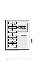
Page 47: ...d the RCA Configuring the RCA Create configuration entry Configuring the LAN console Configuration entry correct Next configuration entry Delete configuration entry Process setup data Activate BOOTP service Switch on RCA Save setup data mklancon no yes rmlancon showlancon yes no vi RCA_config_file mkrca rsh setup ...

Page 48: ...RCA notifying this system name to the DNS server Domain Name Service if applicable If the LAN Console and the RCA are located in different subnets the gateway between them must pass the bootp requests This has to be set beforehand in the router Obtain the following information on the LAN Domain name Subnet mask of the RCA If a gateway has been set up IP address of the gateway into the subnet of th...

Page 49: ...f the RM or PRIMEPOWER MR server as the console name The opt SMAW SMAWxsco sbin showlancon script checks the configuration entries that are created Configuration entries can be removed with the aid of opt SMAW SMAWxsco sbin rmlancon If parameters for a configuration entry need to be changed this entry has to be deleted and recreated with the new data Commands For each of these commands there is a ...

Page 50: ...with y RCA PortNumber If a configuration entry is found for the specified TCP IP port number which is served by the RCA it is displayed and can be removed with y n ConsoleName The configuration entry belonging to the specified symbolic system name is output and can be removed with y a All configuration entries on the LAN Console are displayed and can be removed with y showlancon Displaying specifi...

Page 51: ...which the RCA is shipped ensures that the necessary setup information is loaded from a boot server the first time the RCA is booted Since the RCA does not have a keyboard or display of its own the LAN Console assumes the role of the boot server The necessary setup data for the RCA has to be made available and the BOOTP service has to be activated on the LAN Console The RCA is thus configured in th...

Page 52: ...in the shell comments are preceded by Template file opt SMAW SMAWxsco misc setup tpl Configuration Template for RCAs setup ini fill in like KEY value ethernet address 6 2 digit hex values separated by a colon 00 FF ip address 4 numeric values separated by a dot 0 255 _____________________________________________________________ RCAs network configuration RCA_MAC ethernet HW address of RCA 08 00 06...

Page 53: ... no 0 1 TCP_Port_3002 no yes default no 0 1 TCP_Port_3003 no yes default no 0 1 TCP_Port_3004 no yes default no 0 1 TCP_Port_3005 no yes default no 0 1 TCP_Port_3006 no yes default no 0 1 What has been described so far is a general overview of configuration What fol lows is a step by step guide Ê The following entries have to be made in your work file RCA_config_file Keyword Comment Example RCA_MA...

Page 54: ...uration entries for gateways DNS Domain Name Service and TCP ports are checked for 0 1 If no entry exists 0 is taken as the default value The names for the RCA host and the domain must contain a string If DNS is wanted for the RCA then the IP addresses of the required DNS serv ers must also be entered If the RCA is going to be operated without DNS then the IP address and host name of the LAN Conso...

Page 55: ...N Console in its capacity as a BOOTP server Switching on the RCA The supplied setup data is made available in the RCA when the device is switched on the first time After booting the RCA must be addressable in the network by means of a ping command from the LAN Console The setup data that is transferred during the boot process must now be stored in the RCA in order to take effect after every reboot...

Page 56: ... on the first screen page after access control see the section Language Keyboard on page 91 I The RCA configuration parameters can be extended and changed con veniently with a remote setup using the X user interface see Appendix on page 89 The setup data that is stored on the boot server is still available when the RCA has been booted i e if the RCA were to be rebooted without the setup data being...

Page 57: ... page 41 and Commands on page 43 A password has to be assigned in mklancon to the specified port for each new entry This password has to be notified to the RCA by entering it under the Configuration entry for port number RCA New ports on the LAN console Configuration entry correct Another configuration entry Delete configuration entry Remote setup Password for port number RCA Another port number R...

Page 58: ...to do this as described in the section Initial configuration of the LAN Console and RCA on page 42 Finally the RCA has to be activated as described under BOOTP service for RCA on page 48 and Switching on the RCA on page 49 6 2 4 Another LAN Console connected to the RCA To configure another LAN Console connected to an existing RCA all configura tion entries for the existing LAN Console must also be...

Page 59: ...ual If you are using the LAN Console on a PRIMEPOWER MR the line speed for the connected port of the RCA must be set in the RCA setup to 9600 baud see the section Ports in the Appendix 6 2 5 3 Removing a LAN Console Ê Delete all configuration entries for example using opt SMAW SMAWxsco sbin rmlancon a Ê Remove any host entries for the LAN Console from every connected RCA Ê Disable the BOOTP servic...

Page 60: ...ropriate remove the network data for all connected LAN Consoles or put it back into the state it was in upon delivery see the section Diagnos tics on page 83 Ê In every connected LAN Console delete all configuration entries for this RCA and disable the BOOTP service see the section Diagnostics on page 83 ...

Page 61: ...h a detailed release notice that you can find under opt readme telesv d fgm00 There is also a HELP function for every menu item A CHOICES function is available when there are several options You can order a manual for the Teleservice software from your sales partner V Preparatory work for Teleservice Some preliminary work is needed before getting Teleservice started but any user with some technica...

Page 62: ...ar of the modem To avoid con tact problems you should fasten the screws attached to the cable using a small screwdriver Figure 22 Rear of the modem Use the Western TAE cable for the modem telephone connection The Western connector is inserted in the modem and the TAE connector in the tele phone connection socket Note that the TAE connector will only fit in a TAE socket that has an N interface A te...

Page 63: ...llowing set tings and change them if necessary Ê Check the default settings for the useradd 1M command useradd D If the default setting for basedir points to home use useradd D b export home to change this to export home When you have finished these preparations install the Teleservice package SMAWtssv from the system management CD using the pkgadd command 6 3 2 Generating the software The screens...

Page 64: ...e SCL is subject to optional contractual agreements You should contact your sales partner if you would like to use it The relevant ser vice must first be set up so that the modem can be installed Ê From the first menu in the first window choose option d Install Teleservice channel and in the next menu option a Install Modify service at Teleservice channel The physical properties are entered in the...

Page 65: ...s connected to a private automatic branch exchange PABX enter the exchange code outside line code that you dial to make a local or long distance call on the Teleservice connection This is 0 on many PABXs The fields are not filled in for direct connections to the public telephone net work Ê Save these settings by choosing SAVE 6 3 2 2 Selecting validated Teleservice modems If you are connecting a d...

Page 66: ...m mode items are taken from the parameter descriptions for your modem and normally do not need to be changed Ê Exit the menu by choosing SAVE The screen is then refreshed and the following messages are displayed example Modem installation is running please wait Approved firmware revision xxxxxxxxxxxxxxxxxxx Actual firmware revision xxxxxxxxxxxxxxxxxxxxxx Done Press ENTER to continue Ê Confirm this...

Page 67: ...r s mail address blank are preassigned default values for the TeleCall function You will find further information on the topic of TeleCall on the Internet under http its siemens de lobs its its_sc swserv reliant tele call telecall_gr htm or by calling your Service hotline 0180 5 2202 in Germany and quoting the keyword TeleCall Ê Contact person Here you enter the name s of one or more of your emplo...

Page 68: ...aderborn local public network This field is only shown in advance if pabx was entered for Connection between modem and telephone network Ê A further parameter required is the phone number for contacting the relevant Teleservice center A symbolic name can be used here or you can also enter the number directly A symbolic name is converted by the software If the number changes the assignment can be c...

Page 69: ...ng this The text on this screen is variable so the data shown below is just a snapshot When the connection has been established the Teleservice center requests you to enter the required information This includes Ê Terminal type Here you enter the type of terminal from which you will later monitor and possibly suppress all activities that are performed on your system ...

Page 70: ...is neces sary Ê When you have completed the form exit this menu with the SAVE func tion The following screen appears At first only the first two lines appear The rest is output after a successful test this can take a while because con nection establishment and the connection data are tested Ê Pressing ENTER takes you back to the Teleservice Administration menu which you can close by selecting the ...

Page 71: ...onnection or call up the following page on the Internet http its siemens de lobs its its_sc swserv reliant telecall telecall_en htm One of the components of Logging V3 0 is event management Event management is an instrument that defines events on the basis of error messages and the frequency with which they occur and initiates reactions according to these events An event occurs when the number of ...

Page 72: ... German language environment for the software installation you have to set the LANG variable to De_DE 88591 otherwise set it to En_US ASCII 6 4 1 2 Software installation on the LAN Console Ê Install the SMAWtelx software package with the installer command from the system management CD The software package is then installed automati cally Ê You respond as follows to the questions prompted during th...

Page 73: ...wer the questions during installation with yes 6 4 2 Generating the Telecall cluster Before continuing with generation of the TeleCall cluster Ê make sure that the SMAWtelx or SItelx software package has been installed on all machines involved and that the LAN Console has a fully functional Teleservice connection to a Siemens IT Service Teleservice center Ê test this if you need to via the Teleser...

Page 74: ... all subsequent Teleservice activities You will find the identification number on the nameplate on your system unit Ê Change the Automatic Defect Reporting ADM field to yes with the Choices function and in the to center field enter the Teleservice cen ter where your fault reports are to be dealt with Ê Enter your customer information in the other fields V Mandatory fields All fields including Phon...

Page 75: ...ord for SystemName Password for root 4 Check the state of the machines in the TeleCall cluster using the command node_adm LI C telx All machines must be in the INTEGRATED state Example 5 Define the Teleservice machine for the entire cluster with the command event_adm X LAN Console SystemName t TELEX C telx V Adding a new machine This step must also be executed when adding a new machine to an exist...

Page 76: ...his completes generation of the TeleCall cluster You can initiate a test call on the machine to your configured Teleservice center with the LOGPATH reactions calltelex M This is a test call please cancel command in order to perform a function test ...

Page 77: ...rvice is activated for the RCA see BOOTP service for RCA on page 48 Only the RM600 Exx apart from the E20 E60 models from Reliant UNIX V5 45 on can be booted and installed over a LAN Remote boot and installation are not started from the LAN Console s CD drive but from the hard disk The prerequisite for this function is that the SMAWrins package has been installed from the system management CD and ...

Page 78: ... nfs server if etc dfs dfstab contains entries More information on this is given in the NFS Administration Guide for Solaris 3 There must be enough free space in tftpboot to store the boot files sash Miniroot and unix These take up about 30 MB for each operating system version that is going to be installed If there is not enough space an attempt is made with nfs to mount the data from var sadm rem...

Page 79: ... the source patch level object patch level and production level C3004 for 5 43 C30 C1013 for 5 44 C10 This syntax is important because the installation scripts on the RM ascertain precisely this variable from the UNIX that was booted for the installation process and then use this variable to search through the path on the server for the data for the required NFS Network File System mount Parameter...

Page 80: ...der var sadm remote 6 Write entry in etc dfs dfstab and NFS sharetab for the installation directory var sadm remote or the directory to which the symbolic link points 7 Copy the boot files to tftpboot or tftpboot VERSION If the tftpboot does not have enough space for the copy this is detected and reported There are the following possibilities at this point An attempt is made with nfs to mount var ...

Page 81: ... 3 S KS 34dhcp are deleted the dhcpd options in etc init d dhcp are reset and the etc default dhcp configuration file is deleted Procedure in the system 1 Stop the DHCP service if it is running 2 Create the etc default dhcp file 3 Enter the dhcpd options in etc init d dhcp o 10 b manual 4 Create the DHCP service configuration table var dhcp dhcptab with dhtadm C 5 Create the local DHCP network tab...

Page 82: ...hexadecimal numbers between 0 and ff separated by g GATEWAY_ADDR The IP address of the gateway to the subnet in which the RM client is located This parameter must be specified if the RM client is not in the same subnet as the Solaris computer It can be omitted if the two sys tems are in the same subnet This is specified in the usual Internet for mat xxx xxx xxx xxx decimal numbers separated by s S...

Page 83: ... file relative to the tftp home directory Example tftpboot is the tftp home directory defined by the entry in etc inetd conf Y4B0033 sash_b20 is then the relative path of the boot file CLIENT_NAME The name host name of the client Format 2 add_RM_client D CLIENT_NAME A client for the BOOTP service is deleted on a Solaris system with the add_RM_client tool Options D CLIENT_NAME This call removes the...

Page 84: ...h pntadm C yyy yyy yyy yyy if the client is in a different subnet to the server 6 Create or update the local or remote LAN macro in var dhcp dhcptab with dhtadm A m xxx xxx xxx xxx d Subnet SUBNET_IP Router GATEWAY_IP 7 Enter the client information in the local or remote DHCP network table var dhcp xxx_xxx_xxx_xxx or var dhcp yyy_yyy_yyy_yyy with pntadm A IP_ADDR f BOOTP h CLIENT_NAME i ETHER_ADDR...

Page 85: ...rnel Debugger BDM Board Debug Monitor and OBP Monitor RM or PRIMEPOWER MR servers can also be rebooted from the LAN Console 7 1 xscon call Access to the RM and PRIMEPOWER MR servers is provided by xscon SMAWxsco package and the necessary connection is selected and established internally via rtty SMAWrtty package To establish this connection both xscon and rtty require data which is defined when th...

Page 86: ...able systems are the con sole names that were specified in the mklancon script when the configuration entries were created The xscon user interface can also be chosen via the Solaris Common Desktop Environment where there is a corresponding entry in the Application Manager The connection is established basically in the same way as for cu 1 The connection is cleared down via the string xscon mappin...

Page 87: ...e 83 The log file will be created and stored on the system on which xscon was started If the SMAWtssv package has also been installed you can choose from a menu whether or not you want to use Teleservice A console window is opened for each connection If the connection to the RCA cannot be established within 10 seconds an error message is output and the console window is closed xscon supports up to...

Page 88: ...e If you are using a private copy of xmbind alias in the home directory you must also copy usr dt lib bindings sun_at to the home directory 7 2 Switching LAN Consoles The LAN Console is switched when representation of consoles from RM or PRIMEPOWER MR servers i e console access to these systems is to be handled from another LAN Console in the future The connection to the RM and PRIMEPOWER systems ...

Page 89: ... tion on resetting such connections 7 3 Diagnostics This section provides information on the diagnostic facilities in the LAN Console product It describes logging properties of the rtty monitor and the internal impact of creating configuration entries It goes on to describe diagnostic options and error situations involving the RCA 7 3 1 Log files When the LAN Console is configured the rtty monitor...

Page 90: ...nconsole _shadow files Under the specified console name the _pmtab file contains information about the device used the system name and port number of the RCA as well as inter nal rtty details of the type of connection For each console name the _shadow file contains the encrypted password for accessing the RCA This information on configuration entries can be displayed with showlancon or with the sy...

Page 91: ...om the Systems and Devices files 7 3 4 System information for the RCA The System Information screen page in the RCA setup routine shows among other things the current firmware version and the Ethernet address of the RCA See the Appendix on page 89 and the section System information on page 105 ...

Page 92: ...vice that was activated under BOOTP service for RCA on page 48 You do this with the following command opt SMAWrins bin add_RM_client D RCA SystemName You can now correct the setup data as described under Preparing the setup data on page 45 or in the work file that was created as described in this section Then you have to carry out the actions described in BOOTP service for RCA on page 48 7 4 2 Fai...

Page 93: ...e has been detached or that the connection from the RCA to the LAN has not been working for some time Reset using a command Hanging or open socket connections can be closed using a command The user root enters the following command on the LAN Console that set up the connec tion rsh RCA SystemName resetport RCA PortNumber This command can also be input on a different LAN Console or system by the us...

Page 94: ... c dev rtty line line is derived from the entry under DEVICE from the output of the com mand showlancon n ConsoleName ConsoleName is the symbolic system name of the target system 7 4 4 Invalid password for RCA setup It is only possible to access the RCA setup routine and thus change connection parameters that have been defined for the RCA by entering a valid password 7 4 5 Incorrect remote call of...

Page 95: ...le rsh RCA SystemName setup display SystemName LAN Console 0 I For this remote RCA call make sure that the RCA has access to the LAN Console s X server This access permission is allocated with the xhost RCA SystemName command The xhost command has to be repeated whenever the user logs in This xhost command is also executed in the mkrca script see Configuring the RCA on page 45 because remote call ...

Page 96: ...90 U41224 J Z916 1 76 Access control Appendix 8 1 Access control ...

Page 97: ...inistrator password If you do this the setup routine can only be called by entering this password Any blanks at the end of the password are ignored User Password Here you can input a user password If you do this the setup routine can only be called by entering this password or the system administrator password Only characters from the standard set can be used for the user password i e no umlauts s...

Page 98: ...ndix Access rights after entry of the user password apply to just some of the func tions of the setup routine Functions that are not available to a user who has input the user password but only to the system administrator are grayed on the screen ...

Page 99: ...s also configured on this screen page changes too also refer to the description of the Net Mask option Pay attention to the following advice when allocating IP addresses I An IP address must not be allocated more than once If this happens there can be considerable problems with terminal operations These problems may not become apparent immediately These problems may also arise even if the devices ...

Page 100: ...to matic adjustment does not correspond to the particular conditions of your net work you have to enter the required net mask yourself Your network adminis trator will be able to tell you what is required Gateways It is necessary to specify gateways for connections between the RCA and sta tions that are in a different logical segment of the LAN Enter one or more gate ways here Type the address of ...

Page 101: ...word has to be input in both fields otherwise an error message is output Any blanks at the end of a password are ignored Port Settings For When you have selected the port its settings are displayed Click the circle next to the port name if you want to see the settings for another port The parameters in the fields Parity Stop Bits etc have to be set as required ...

Page 102: ...ton making the port available for the next TCP connections that need to be established V Abort active connections This function will also reset or terminate an active connection An error message is output if there is no connection on the selected port 8 5 Mouse The settings on this screen page are only relevant for a mouse that is connected locally to the RCA ...

Page 103: ...U41224 J Z916 1 76 97 Appendix Graphics Screen 8 6 Graphics Screen The settings on this screen page are only relevant for a display that is connected locally to the RCA ...

Page 104: ...98 U41224 J Z916 1 76 DPMS Appendix 8 7 DPMS The settings on this screen page are only relevant for a display that is connected locally to the RCA ...

Page 105: ... name was specified previously an IP address has to be assigned to this name The names of specified hosts servers are shown in the scroll list at the top The name of the currently selected host server is highlighted Name You can change the name of the selected host server here IP Address You can specify the IP address Internet address of the selected host server here ...

Page 106: ...e The host server entry that you have selected in the list is deleted when you click this button Use DNS Instead of specifying a series of hosts servers and their IP addresses for each RCA you can get the IP addresses from a central computer that runs the DNS service Domain Name Server Local Name You have to enter your local name if you chose the Use DNS option Domain Here you have to specify the ...

Page 107: ...U41224 J Z916 1 76 101 Appendix Hosts DNS This new address then appears in the scroll list To delete a DNS server entry select its name from the list and click the Delete button ...

Page 108: ...102 U41224 J Z916 1 76 Sessions Appendix 8 9 Sessions Local Telnet sessions can be set up here This mode is not supported in RCA ...

Page 109: ...w firmware is located I The server name entered in the screen output is only provided as an example as is the case with the other name address and path details in the respective input boxes Remote Path Here you can specify the directory on the server in which the firmware images are stored User Here you can specify the name of the user who is entitled to access the firmware images ...

Page 110: ...ngs that have been defined in the setup routine are saved in the same way as for the Save option on the Exit screen page and the new firmware is downloaded from the specified server The terminal is restarted several times during this operation When the update has been completed successfully a new firmware version number appears on the System Information screen page Restore Factory Defaults If you ...

Page 111: ...U41224 J Z916 1 76 105 Appendix System information 8 11 System information RCA system information is output on this screen page ...

Page 112: ...en defined in the setup routine You can choose between Save and Discard Save All settings are saved and control returns to the normal RCA mode In the case of certain changes it is necessary to restart the RCA for them to take effect You are asked in each case whether or not you want to restart the RCA Discard If you select this option on the Exit screen page none of the settings is saved and contr...

Page 113: ...U41224 J Z916 1 76 107 Appendix Restart 8 13 Restart This query lets you decide whether or not you want to restart the RCA ...

Page 114: ......

Page 115: ...console A control unit that gives the user direct access to a computer DNS Domain Name Service MAC Media Access Control Hardware address for accessing a device NIS Network Information Service Central administration of configuration information in a network For instance IP addresses security details mail Ethernet interface configurations and other network services can be administered or provided ce...

Page 116: ......

Page 117: ... CPU Central Processing Unit CSA Canadian Securities Administrators CTS Clear to Send DHCP Dynamic Host Configuration Protocol DNS Domain Name Service DTR Data Terminal Ready signal EN European norm FCC Federal Communications Commission GS German certification Geprüfte Sicherheit IEC International Electronical Commission ...

Page 118: ...r IP Internet Protocol LAN Local Area Network MAC Media Access Control NFS Network File System OBP Open Boot Prom Program PCI Peripheral Component Interconnect RCA Remote Communication Adapter RMS Reliant Monitor Software RTS Request To Send RTTY Remote TeleType SCL Secure Communication Layer SCS System Console Software ...

Page 119: ...e Processor Architecture SunVTS Sun Validation Test Suite TCP IP Transmission Control Protocol Internet Protocol TFT Thin Film Transistor UL Underwriters Laboratories Incorporated USB Universal Serial Bus VGA Video Graphic Adapter VTS see SUNVTS WSA Web based System Administration ...

Page 120: ......

Page 121: ...allation of it when there is a new system disk 2 Reliant UNIX 5 45 Reliant UNIX Operation System Administrator s Guide Target group System administrators Content Description of the administration of Reliant UNIX 3 Reliant UNIX 5 45 Commands Target group Shell users Content This document describes the Reliant UNIX commands in alphabetic order 4 Reliant UNIX 5 45 User Guide Target group Users Conten...

Page 122: ... Target group System administrators Content This manual provides an introduction to UNIX system administration Among other things it describes the system administrator tools UNIX system configuration and support calculation of system usage as well as aspects of system security The manual applies both for MIPS based UNIX and for Intel based UNIX 7 Reliant UNIX 5 45 Error Diagnostics and Troubleshoo...

Page 123: ...nds functions utilities and system files which are required for working with networked computers 10 Reliant UNIX 5 45 RM 600E Operating Instructions Target group System administrators Content This document provides information on the multi user RM600E computer system running under Reliant UNIX 5 45 11 Reliant UNIX 5 45 RM 600 E40 E42 E80 CS42 Operating Instructions Target group System administrato...

Page 124: ...ystem administrators Content Description startup and operation of the RM ServerNode multiprocessor computer system with the Reliant UNIX 5 45 operating system 14 Reliant Monitor Software V3 1 Installation of RMS Reliant UNIX and Solaris System Administrator s Guide Target group System administrators Content This is a guide to installing the Reliant Monitor Software RMS on Sie mens RM systems 15 Re...

Page 125: ...figuration and administra tion of the Reliant Monitor Software RMS 17 Reliant Monitor Software V3 1D RMS Concepts Reliant UNIX and Solaris System Administrator s Guide Target group System administrators Content This document describes the concepts of the RMS product 18 Reliant UNIX 5 45 High Availability System Administrator s Guide Target group System administrators Content Description of the har...

Page 126: ...ons Target group System administrators engineers Content Safety instructions in 12 languages for rack systems 22 Reliant UNIX Solaris WebSysAdmin Domain Admin 2 0 System Administration within a Domain Target group System administrators service technicians Content Bundling and administration of several computer nodes using WSA Web based System Administration and Domain Admin Solaris publications 23...

Page 127: ...of the Netra AX1105 500 CPU board its operation displays connections boot sequences and specifi cations PRIMEPOWER publications 26 GP 7000F PRIMEPOWER Systems Safety Instructions Target group System administrators technicians Content Safety brochure in eighteen languages for the GP 7000F PRIMEPOWER systems 27 PRIMEPOWER Solaris PRIMEPOWER 2000 1000 800 System Management Console SMC User Guide Targ...

Page 128: ...rget group Technicians Content Installation instructions for the PRIMEPOWER M200 system 30 PRIMEPOWER Solaris Model 400 Installation Instructions Target group Technicians Content Installation instructions for the PRIMEPOWER M400 system 31 PRIMEPOWER Solaris Model 600 Installation Instructions Target group Technicians Content Installation instructions for the PRIMEPOWER M600 system 32 PRIMEPOWER So...

Page 129: ...EPOWER Solaris Model 400 Maintenance Manual Target group Technicians Content Service Manual for the PRIMEPOWER M400 system 34 PRIMEPOWER Solaris Model 600 Maintenance Manual Target group Technicians Content Service Manual for the PRIMEPOWER M600 system ...

Page 130: ......

Page 131: ...ing 29 console 34 order numbers 32 CCU 1 CDE 24 CE conformity 14 client deleting 71 setting up 71 climatic class 13 cluster 2 Combo controller 7 common desktop environment 24 configuration LAN Console 39 RCA 39 configuration files 75 connection aborted 87 cable 32 clearing down 80 devices 17 disrupted 87 external devices 16 17 hanging 87 LAN Console 17 to LAN 2 32 to PRIMEPOWER 32 to RM system 32 ...

Page 132: ...s 53 ethernet 30 address 76 exhaust air clearance 36 external devices connect 17 connection 16 F FCC 14 firmware update 103 firmware images password 104 firmware version RCA 85 G GP7000F 1 H hard disk indicator 22 hard disk partitioning 23 hardware RCA 29 hardware address 76 86 host name 24 I important information 5 installing telecall 66 interface 18 internal kernel debugger 7 79 IP address 86 K ...

Page 133: ...91 user 91 PATH 27 pmadm rtty monitor 84 port password 95 port number RCA 43 ports 39 power consumption 12 power LED 22 power supply 12 connecting 20 setting 19 PRIMEPOWER 1 connection cable 32 connection to RCA 32 enterprise server 23 models 100 200 400 600 1 models 800 1000 2000 1 23 processor 11 prom monitor 7 79 R rack console 10 rack module 9 rated voltage 12 RCA configuration 39 connection t...

Page 134: ...lement CD 25 switching off LAN Console 21 switching on LAN Console 21 system console 1 7 cabling 34 software 25 System Console Software 7 system console software 1 11 System Management Console 7 system management console 11 23 T TCP IP RCA 29 technical customer service communication 2 teleadm 67 telecall installation 66 telecall gateway 2 teleservice 2 26 software installation 57 template file 46 ...

Page 135: ...urieren und Bedienen U41224 J Z916 1 Comments Suggestions Corrections Submitted by Fujitsu Siemens Computers GmbH User Documentation 33094 Paderborn Germany Fax 49 700 372 00001 email manuals fujitsu siemens com http manuals fujitsu siemens com ...

Page 136: ......

Page 137: ...urieren und Bedienen U41224 J Z916 1 Comments Suggestions Corrections Submitted by Fujitsu Siemens Computers GmbH User Documentation 33094 Paderborn Germany Fax 49 700 372 00001 email manuals fujitsu siemens com http manuals fujitsu siemens com ...

Page 138: ......
Page 139: ...tsu com Copyright Fujitsu Technology Solutions 2009 Hinweise zum vorliegenden Dokument Zum 1 April 2009 ist Fujitsu Siemens Computers in den alleinigen Besitz von Fujitsu übergegangen Diese neue Tochtergesellschaft von Fujitsu trägt seit dem den Namen Fujitsu Technology Solutions Das vorliegende Dokument aus dem Dokumentenarchiv bezieht sich auf eine bereits vor längerer Zeit freigegebene oder nic...

Reviews: