background image

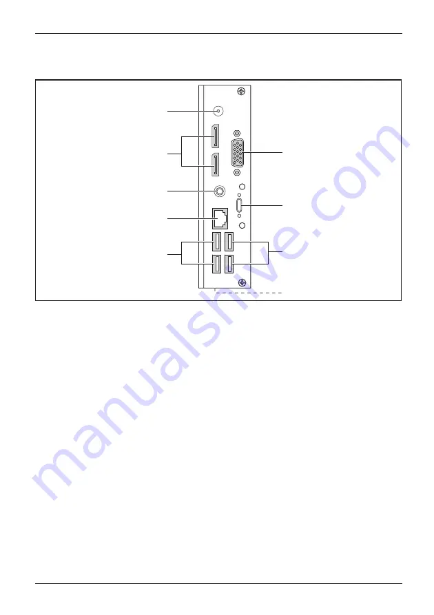
Ports and Operating Elements

Rear view

LANsocket

Monitorport

USBports

powersupply

DCinputconnector

SecurityLock

SecurityLockdevice

USB

Serialport

Displayport

1

2

3

9

6

7

8

5

4

1 = Serial port (optionally only for the

FUTRO S7010)

2 = Device without Power-over-Ethernet

module: USB 3.1 Gen1 port (USB Type-C,
optional) with double screw security
Device with Power-over-Ethernet
module: No port

3 = USB 2.0 ports (USB Type-A)

4 = Security Lock

fi

xture (positioned

at the side)

5 = USB 2.0 ports (USB Type-A)
6 = RJ45 socket (Local Area Network)
7 = Audio output (Line out)
8 = DisplayPort
9 = DC input jack (DC IN)

Fujitsu

7

Summary of Contents for FUTRO S5010

Page 1: ...Thin Client Operating Manual FUJITSU Thin Client FUTRO S5010 FUTRO S7010 ...

Page 2: ...lable on our website http www fujitsu com fts You can find driver updates at http support ts fujitsu com download Should you have any technical questions please contact our Hotline Service Desk http support ts fujitsu com contact servicedesk Your sales partner Your sales office We hope you enjoy using your new Fujitsu system ...

Page 3: ......

Page 4: ...jitsu Technology Solutions GmbH Mies van der Rohe Straße 8 80807 Munich Germany http www fujitsu com fts Copyright Fujitsu Technology Solutions GmbH 2019 All rights reserved Publication Date 12 2019 Order No A26361 K1080 Z329 1 7619 edition 1 ...

Page 5: ... Thin Client FUTRO S5010 FUTRO S7010 Operating Manual Your FUTRO 5 Ports and Operating Elements 6 Important notes 11 Getting started 14 Operation 23 System expansions and repairs 28 Technical data 29 Index 31 ...

Page 6: ...demarks of ACCO Brands USB Type C and USB C are trademarks of the USB Implementers Forum in the USA and other countries Microsoft and Windows are trademarks or registered trademarks of Microsoft Corporation in the USA and or other countries eLux and Scout Enterprise Management Suite are registered trade marks of Unicon Software Entwicklungs und Vertriebsgesellschaft mbH in the European Union and i...

Page 7: ...7 Connecting external devices 19 Ports on the device 19 Connecting a monitor 19 Connecting a USB mouse 20 Connecting a USB keyboard 20 Connect external devices to the serial port optional 20 Connecting external devices to the USB ports 21 Connect microphone and headphones 21 Connecting the device to the network LAN 21 Connecting the mains adapter 22 Operation 23 Switch the device on 23 Operating s...

Page 8: ...Contents FUJITSU Thin Client FUTRO S5010 S7010 29 AC adapter 30 Index 31 4 Fujitsu ...

Page 9: ...evice Indicates an activity that must be performed Indicates a result This font indicates data entered using the keyboard in a program dialogue or at the command line e g your password Name123 or a command used to start a program start exe This font indicates information that is displayed on the screen by a program e g Installation is complete This font indicates terms and texts used in a software...

Page 10: ...s will provide you with an overview of the ports and operating elements on the device Please familiarise yourself with these components before you start to work with the device Front view Onswitch Offswitch Headphoneport Microphonejack USB 1 2 3 4 1 ON OFF switch 2 USB 3 1 Gen1 ports USB Type A 3 Headphone port 4 Microphone jack 6 Fujitsu ...

Page 11: ...tionally only for the FUTRO S7010 2 Device without Power over Ethernet module USB 3 1 Gen1 port USB Type C optional with double screw security Device with Power over Ethernet module No port 3 USB 2 0 ports USB Type A 4 Security Lock fixture positioned at the side 5 USB 2 0 ports USB Type A 6 RJ45 socket Local Area Network 7 Audio output Line out 8 DisplayPort 9 DC input jack DC IN Fujitsu 7 ...

Page 12: ...or protecting your device and your personal data from unauthorised access You can also combine these functions Security Lock device You can use the security lock device positioned at the side and the Kensington Lock cable steel cable accessory to protect your device against theft Please consult the manual for your security lock When using the Security Lock device opening of the casing is also prev...

Page 13: ...optional USB covers to the USB ports on the front and rear side of the device Please note that USB covers once fitted cannot be removed again Ensure that you fit the USB covers the right way round Insert the USB covers in the USB ports on the front of the device and push the USB covers in firmly Fujitsu 9 ...

Page 14: ...the USB covers in the USB ports on the rear side of the device and push the USB covers in firmly In the BIOS Setup under Advanced USB Port Security you can also deactivate the USB ports in order to limit the use of USB devices 10 Fujitsu ...

Page 15: ...Some of the activities described in this manual may only be performed by authorized personnel Improper repairs may cause danger to the user electric shock fire hazard or material damage to the unit Operate the device only with the casing closed Power cable and mains adapter The supplied power cable conforms to the requirements of the country in which you purchased your device Make sure that the po...

Page 16: ...ent of the external interfaces must be checked or reduced If the system does not receive the required power according to standard 802 3 at 25 5 W the system stops in the post with an error message In this case check your midspan or end span device Transporting the device Device Transportation Retransportation Transport all parts separately in their original packaging or in a packaging which protec...

Page 17: ...ting When the WoL functions are active the maximum permissible power draw can be exceeded slightly in OFF mode By deactivating the WoL function it is possible to comply with the legal requirements Please see chapter Activating power saving mode Page 26 for the procedure The energy saving mode ACPI S4 Save to disk which is familiar from many current mobile and desktop systems is not available in th...

Page 18: ...to ensure that the casing is sufficiently ventilated and to prevent overheating the device must only be operated with the base foot attached If the device is to be built in adequate ventilation must be assured Fit the base feet for horizontal or vertical operation see Vertical operating position Page 15 and Horizontal operating position Page 17 14 Fujitsu ...

Page 19: ...t the device is in a stable position in order to prevent it from toppling over Proceed as follows to prepare the device for the vertical operating position Disconnect the cables if required Lay the device on its top narrow side as shown on a stable flat and clean surface 1 3 3 3 3 1 2 Place the feet on the casing 1 In doing so make sure that the 4 clips 2 on the feet are aligned above the correspo...

Page 20: ...l of the feet the feet can also be secured with two screws each of type M2 5x5 mm These are not included in the delivery scope Secure the feet with the screws 3 Stand the device on the feet If necessary reconnect any cables that were previously disconnected 16 Fujitsu ...

Page 21: ...Disconnect the cables if required Lay the device on its right side as shown on a stable level and clean surface 2 1 1 3 3 3 3 Fit the feet on the housing 1 Make sure that you align the 4 clips 2 on the feet with the corresponding openings in the housing To fix the feet press the clips in the direction of the arrow 2 until they engage noticeably in the openings To protect your device against unauth...

Page 22: ...Getting started Place the device on the feet If necessary reconnect any cables that were previously disconnected 18 Fujitsu ...

Page 23: ...ts are marked with the symbols shown below or similar Headphone port black front of device Headphoneport Headphones Microphone port black front of device Microphoneport Microphone RJ45 LAN port LANport Serial port Serialport USB 3 1 Universal Serial Bus Gen 1 Type A blue Gen1 type C black UniversalSerialBus DP DisplayPort USB 2 0 Universal Serial Bus type A black Audio output Line Out black Audioo...

Page 24: ...rnal devices to the corresponding port please see the external device documentation External devices e g a printer or scanner can be connected to the serial port Connect the data cable to the external device Connect the data cable to the corresponding serial interface Port settings Serialinterface You can change the settings of the port in the BIOS Setup Device drivers Devicedrivers The devices co...

Page 25: ...al device Connect the data cable to one of the USB ports on your device Device drivers External USB devices which you connect to one of the USB ports don t usually need their own drivers because the software required is already included in the operating system If the device requires separate software please follow the instructions in the manufacturer s documentation Connect microphone and headphon...

Page 26: ...ower cable conforms to the requirements of the country in which you purchased your device Make sure that the power cable is approved for use in the country in which you intend to use it 2 1 3 Connect the mains cable 1 to the mains adapter Connect the mains adapter cable 2 to the DC jack DC IN of the device Plug the mains cable 3 into a mains socket 22 Fujitsu ...

Page 27: ... be managed with the Scout Enterprise management solution eLux The eLux Thin Client operating system is based on Linux and is protected against viruses and malware by the write protected file system It has a lean and modular structure and thus has low demands on the hardware It enables access to the server via the integrated Citrix and Microsoft clients as well as the optional VMware client It has...

Page 28: ...roduct in a single article No license is granted or will be implied for any other use Additional information may be obtained from MPEG LA LLC See www mpegla com To the extent that non Product software includes AV Technologies licensed by MPEG LA LLC under a product category such license agreement will determine any royalties due for AV Technologies included in non Product software This Product inc...

Page 29: ...mation Display of installed or connected components such as mainboard memory display adapters monitors and USB devices User friendliness and handling Simple and intuitive operation Automatic updates of eLux packages Complete audit reporting Help Desk support Support of Wake On LAN and Remote Power On Off Mirroring of desktops encrypted and audit proof Extensive diagnostic information For more info...

Page 30: ... the requirements of EC regulation 1275 2008 regarding the implementation of the Ecodesign directive 2009 125 EC the default WoL setting must be changed as follows To start the BIOS Setup utility after the system start press the ON OFF switch for two to three seconds or Press the F2 function key In the Power sub menu change the External Power Button Control LAN and Keyboard to disabled To save the...

Page 31: ...m that cannot be solved using new drivers or new software Where can I obtain BIOS updates You can find the BIOS updates on the Internet at http support ts fujitsu com Making system settings Make the system settings as described in the documentation for your operating system Executing a system update There are two ways of updating your system software via the Unicon Product Scout Enterprise via an ...

Page 32: ...n the Internet in the System Expansions and Repairs manual at http www fujitsu com fts support Operations that are distinguished in the manual as Only For Service such as repairs to the device may only however be performed by authorised service technicians Incorrect repairs may greatly endanger the user electric shock fire risk and will invalidate your warranty 28 Fujitsu ...

Page 33: ...mm x 175 mm x 158 mm 2 99 inch x 6 89 inch x 6 22 inch Width x Depth x Height without foot 36 mm x 165 mm x 147 mm 1 42 inch x 6 48 inch x 5 78 inch Dimensions horizontal operating position Width x Depth x Height with foot 187 mm x 175 mm x 47 mm 7 35 inch x 6 89 inch x 1 85 inch Width x Depth x Height without foot 147 mm x 165 mm x 36 mm 5 78 inch x 6 48 inch x 1 42 inch Weight in basic configura...

Page 34: ...ted voltage 100 240 V Max rated current 1 85 A Rated frequency 50 60 Hz Only the following adapters with Limited Power Source may be used S26113 E622 V55 Model ADP 40HH A S26113 E623 V55 Model ADP 65JH AB CP500624 01 Model A12 065N2A A 30 Fujitsu ...

Page 35: ...cting 20 21 G Getting started 14 H Headphone port 6 19 Headphones 19 connecting 21 Horizontal operating position 17 I Important notes 11 L LAN 21 LAN port 19 LAN socket 7 Line out 19 M Microphone 19 connecting 21 Microphone jack 6 Microphone port 19 Monitor port 7 Monitor Connecting 19 switching off 26 switching on 23 N Note safety 11 Notes important 11 O Off switch 6 On switch 6 Operating positio...

Page 36: ...erial port 7 19 Servicing 28 Side cover 15 System expansion 28 System unit see Device 12 T Technical data 29 Transportation 12 U Universal Serial Bus 19 Upgrades device 28 USB 7 USB devices connecting 21 USB port 20 connecting keyboard 20 USB port connecting devices 21 USB ports 7 USB ports 6 V Vertical operating position 15 32 Fujitsu ...

Reviews: