7-14
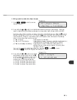
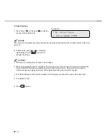
17. Adjust ADF Erasing Edges
<Screen 57>
1
Press “Next”
or “Previous”
and let
the scanner display Screen 57.
2
At Screen 57, press
or
to select
“Yes” and press
. Then the scanner
displays Screen 57-1.
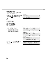
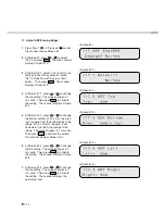
<Screen 57-1>
3
At Screen 57-1, select “Yes” to return the
settings to the factory default or select
“No” to make new settings (as shown
below). Then press
. The scanner
displays Screen 57-2.
<Screen 57-2>
4
At Screen 57-2, press
or
to change
the top setting. The value changes in 1
mm units. Then press
to activate
the setting. The scanner displays Screen
57-3.
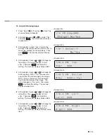
<Screen 57-3>
5
At Screen 57-3, press
or
to change
the bottom setting. With (+:Up), the area
is set upward from the bottom edge of the
image. With (–:Down), the area is set
downward from the bottom edge of the
image. The value changes in 1 mm units.
Then press
to activate the setting.
The scanner displays Screen 57-4.
<Screen 57-4>
6
At Screen 57-4, press
or
to change
the left setting. The value changes in 1
mm units. Then press
to activate
the setting. The scanner displays Screen
57-5.
<Screen 57-5>
7
At Screen 57-5, press
or
to change
the top setting. The value changes in 1
mm units. Then press
to activate
the setting. The scanner displays the
next setup item.
Summary of Contents for fi-4750L
Page 1: ...Operator s Guide fi 4750L Image Scanner C150 E200 02EN ...
Page 2: ...fi 4750L Image Scanner Operator s Guide ...
Page 10: ...viii ...
Page 23: ...1 11 Image transfer alarm Memory alarm EEPROM alarm FAN alarm IPC Board alarm ...
Page 24: ...1 12 ...
Page 44: ...3 10 ...
Page 57: ...5 3 unit mm Dimensions ...
Page 58: ...5 4 ...
Page 67: ...6 8 ...
Page 84: ...7 16 ...
Page 90: ...GL 6 ...
Page 93: ...DE 1 Declarations of Conformity ...
Page 94: ...DE 2 ...
Page 95: ......


