background image

1.2

Drive Enclosure (3.5" Type)

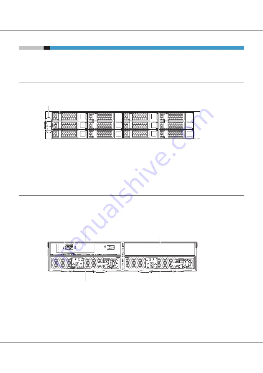
Drives and an operation panel are installed in the front of the drive enclosure. I/O modules and power supply
units are installed in the rear.

1.2.1

Front

This section provides the names of the components in the front of a drive enclosure.

Figure 1.5  Front View of a Drive Enclosure

1

3

3

2

1.

Operation panel

2.

3.5" drive

3.

Flange cover

1.2.2

Rear

This section provides the names of the components in the rear of a drive enclosure.

When only one I/O module is installed

Figure 1.6 Rear View of a Drive Enclosure (When Only One I/O Module is Installed)

3

4

1

5

6

2

1.

I/O module (IOM#0)

2.

Cover

3.

Drive interface (IN) port

4.

Drive interface (OUT) port

5.

Power supply unit (PSU#0)

Chapter 1 Component Names
1.2 Drive Enclosure (3.5" Type)
 

21

FUJITSU Storage ETERNUS DX60 S3 Disk storage system Configuration Guide (Basic)

Copyright 2014 FUJITSU LIMITED

P3AM-9002-01ENZ0

Summary of Contents for ETERNUS DX60 S3

Page 1: ...FUJITSU Storage ETERNUS DX60 S3 Disk storage system Configuration Guide Basic P3AM 9002 01ENZ0 ...

Page 2: ...This page is intentionally left blank ...

Page 3: ...er describes the environment required for system configuration Chapter 4 Connecting Cables page 46 This chapter explains how to connect various cables to the ETERNUS DX Chapter 5 General Settings page 55 This chapter describes the basic settings for the ETERNUS DX Chapter 6 Monitoring Settings page 81 This chapter describes the settings required to monitor the ETERNUS DX Chapter 7 Power Control Se...

Page 4: ...Business Machines Corporation registered in many ju risdictions worldwide VMware VMware logos Virtual SMP and vMotion are either registered trademarks or trademarks of VMware Inc in the U S and or other countries ARCserve products and logos are registered trademarks of CA Technologies The company names product names and service names mentioned in this document are registered trade marks or tradema...

Page 5: ...r Intel 64 Red Hat Enterprise Linux 7 Symbols Used in This Manual The following symbol is used throughout this manual This indicates information for the user to note when using the ETERNUS DX Please be sure to read this information This indicates supplementary and reference information Abbreviations Used in This Manual ETERNUS DX refers to the FUJITSU Storage ETERNUS DX60 S3 Disk storage system CA...

Page 6: ...es IMPORTANT information for the user to note when using the ETER NUS DX The following symbols are used to indicate the type of warnings or cautions being described Electric Shock The triangle emphasizes the urgency of the WARNING and CAUTION contents Inside the triangle and above it are details concerning the symbol e g Electrical Shock No Disassembly The barred Do Not circle warns against certai...

Page 7: ...pe indicator Warning details To avoid damaging the ETERNUS DX pay attention to the following points when cleaning the ETERNUS DX Make sure to disconnect the power when cleaning Be careful that no liquid seeps into the ETERNUS DX when using cleaners etc Do not use alcohol or other solvents to clean the ETERNUS DX Warning layout ribbon Example warning CAUTION Do Preface 7 FUJITSU Storage ETERNUS DX6...

Page 8: ...from the equipment or allow them to become dirty ETERNUS DX60 S3 Controller Enclosures 2 5 Type Controller Enclosure Manufacturer s label The model name and the serial number are listed Device ID label The model name and the serial number are listed Preface 8 FUJITSU Storage ETERNUS DX60 S3 Disk storage system Configuration Guide Basic Copyright 2014 FUJITSU LIMITED P3AM 9002 01ENZ0 ...

Page 9: ...el The model name and the serial number are listed Device ID label The model name and the serial number are listed Preface 9 FUJITSU Storage ETERNUS DX60 S3 Disk storage system Configuration Guide Basic Copyright 2014 FUJITSU LIMITED P3AM 9002 01ENZ0 ...

Page 10: ...Drive Enclosures 3 5 type drive enclosure Preface 10 FUJITSU Storage ETERNUS DX60 S3 Disk storage system Configuration Guide Basic Copyright 2014 FUJITSU LIMITED P3AM 9002 01ENZ0 ...

Page 11: ...ation such as the model name and serial number is indicated Power distribution unit AC200 240V 2U Manufacturer s label Information such as the model name and serial number is indicated Preface 11 FUJITSU Storage ETERNUS DX60 S3 Disk storage system Configuration Guide Basic Copyright 2014 FUJITSU LIMITED P3AM 9002 01ENZ0 ...

Page 12: ...ion for Regions Other than EMEA I 30 2 3 3 5 Type Drive Enclosure Installation for Regions Other than EMEA I 33 Chapter 3 Checking the Configuration Environment 36 3 1 System Configuration Example 36 3 2 Server Connection Preparation 37 3 2 1 Driver Preparation 37 3 2 2 Driver Installation 38 3 2 3 iSCSI Initiator Parameter Settings 39 3 3 Preparing the PC Terminal for Setup 42 3 4 LAN Connection ...

Page 13: ... 61 5 4 Storage Management Initial Setup 1 62 5 5 LAN Cable Connection for Operation Management 67 5 6 Firewall Settings 68 5 7 RAID Configuration Settings 71 5 7 1 RAID Group Creation 71 5 7 2 Operation Volume Creation 73 5 7 3 Generation Management Volume SDV Creation 75 5 7 4 Copy Data Destination Volume SDPV Creation 76 5 7 5 Hot Spare Registration 78 Chapter 6 Monitoring Settings 81 6 1 Event...

Page 14: ...er Connection Setup 115 8 2 1 iSCSI Initiator Parameter Settings Connection Information Settings 115 8 2 2 LUN Recognition Check 124 8 2 3 Disk Partition Settings 126 Chapter 9 Advanced Copy Settings 137 9 1 Advanced Copy Basic Settings 137 9 1 1 Copy Priority Settings 137 9 1 2 Copy Table Size Settings 138 9 1 3 Copy Parameter Settings 140 9 2 Performing a Copy SnapOPC 141 Chapter 10 System Statu...

Page 15: ... Virtualization Platform 154 11 2 1 Oracle VM Linkage 154 11 2 2 VMware Linkage 156 11 2 3 Microsoft Linkage 157 Table of Contents 15 FUJITSU Storage ETERNUS DX60 S3 Disk storage system Configuration Guide Basic Copyright 2014 FUJITSU LIMITED P3AM 9002 01ENZ0 ...

Page 16: ...th SnapOPC 56 Figure 5 2 Example of Creating Operation Volume and Backup Volume 57 Figure 5 3 PC Terminal Connection for Initial Setup 58 Figure 5 4 ON Position Marked of the Main Line Switches on a 1U Power Distribution Unit 58 Figure 5 5 ON Position Marked of the Main Line Switches on a 2U Power Distribution Unit 59 Figure 5 6 ON Position Marked of the PSU Switch on a Power Supply Unit 59 Figure...

Page 17: ...Group Creation 71 Table 5 2 Operation Volume Creation 73 Table 7 1 ETERNUS DX Operation According to the Settings of the Auto Power Function and the Power Resume Function 101 17 FUJITSU Storage ETERNUS DX60 S3 Disk storage system Configuration Guide Basic Copyright 2014 FUJITSU LIMITED P3AM 9002 01ENZ0 ...

Page 18: ...lers and power supply units are installed in the rear 1 1 1 Front This section provides the names of the components in the front of a controller enclosure 2 5 Type Figure 1 1 Front View of a 2 5 Type Controller Enclosure 1 3 3 2 1 Operation panel 2 2 5 drive 3 Flange cover 18 FUJITSU Storage ETERNUS DX60 S3 Disk storage system Configuration Guide Basic Copyright 2014 FUJITSU LIMITED P3AM 9002 01EN...

Page 19: ...ed Figure 1 3 Rear View of a Controller Enclosure When Only One Controller is Installed 1 3 4 5 6 8 9 6 7 2 1 Controller CM 0 2 Cover 3 PWC port 4 Drive interface OUT port 5 LAN RMT port 6 LAN MNT port 7 Host interface CA 0 8 Power supply unit PSU 0 9 Power supply unit PSU 1 Chapter 1 Component Names 1 1 Controller Enclosures 19 FUJITSU Storage ETERNUS DX60 S3 Disk storage system Configuration Gui...

Page 20: ...troller CM 0 2 Controller CM 1 3 PWC port 4 Drive interface OUT port 5 LAN RMT port 6 LAN MNT port 7 Host interface CA 0 8 Power supply unit PSU 0 9 Power supply unit PSU 1 Chapter 1 Component Names 1 1 Controller Enclosures 20 FUJITSU Storage ETERNUS DX60 S3 Disk storage system Configuration Guide Basic Copyright 2014 FUJITSU LIMITED P3AM 9002 01ENZ0 ...

Page 21: ...3 5 drive 3 Flange cover 1 2 2 Rear This section provides the names of the components in the rear of a drive enclosure When only one I O module is installed Figure 1 6 Rear View of a Drive Enclosure When Only One I O Module is Installed 3 4 1 5 6 2 1 I O module IOM 0 2 Cover 3 Drive interface IN port 4 Drive interface OUT port 5 Power supply unit PSU 0 Chapter 1 Component Names 1 2 Drive Enclosure...

Page 22: ...n EMEA I There are two sizes for power distribution units 1U and 2U 1 3 1 Power Distribution Units 1U The 1U power distribution unit has four outlets and two inlets 1 3 1 1 Power Distribution Unit AC200 240V 1U 4 Outlets Figure 1 8 Power Distribution Unit AC200 240V 1U 4 Outlets 3 2 1 1 Main line switch 2 Outlet OUTPUT 3 Inlet INPUT Chapter 1 Component Names 1 3 Power Distribution Units for Region...

Page 23: ...40V 2U 12 Outlets 2 1 1 Main line switch 2 Outlet OUTPUT 1 3 2 2 Power Distribution Unit AC200 240V 2U 16 Outlets There are 16 outlets Figure 1 10 Power Distribution Unit AC200 240V 2U 16 Outlets 2 1 1 Main line switch 2 Outlet OUTPUT Chapter 1 Component Names 1 3 Power Distribution Units for Regions Other than EMEA I 23 FUJITSU Storage ETERNUS DX60 S3 Disk storage system Configuration Guide Basic...

Page 24: ...r cords connec ted The ETERNUS DX contains delicate components and should be handled gently Do not drop or knock the ETERNUS DX against the rack when installing it Also do not knock the other devices installed in the rack The center of gravity must be taken into consideration to prevent a rack from top pling over Enclosures should generally be installed from bottom to top to lower the center of gr...

Page 25: ...es in the following order from bottom to top Rack Controller enclosure Power distribution unit Power synchronized unit Drive enclosure UPS 1 2 3 4 Installation order 2 1 Installing Power Distribution Unit for Regions Other than EMEA I This section describes how to install the power distribution unit in a rack Do Not Do not connect any devices other than the ETERNUS DX to the power distribution uni...

Page 26: ...M6 screw Screw holder Bracket A Holder Holder M6 screw The four M6 screw positions for the brackets are determined relative to the power distribution unit base line The four M6 screws should be inserted in the 1st and 3rd holes above the base line Power distribution unit 1U Rack pillar rear Bracket Power distribution unit base line 1st hole M6 screw 3rd hole M6 screw 1st hole M6 screw 3rd hole M6 ...

Page 27: ...he front side of the rack The blank panel should be attached at the same height as the power distribution unit Rack pillar rear Rack pillar front Blank panel Power distribution unit Chapter 2 Rack Installation 2 1 Installing Power Distribution Unit for Regions Other than EMEA I 27 FUJITSU Storage ETERNUS DX60 S3 Disk storage system Configuration Guide Basic Copyright 2014 FUJITSU LIMITED P3AM 9002...

Page 28: ...in the 1st 3rd 4th and 6th holes above the power distribu tion unit base line 1U 1U 2U Power distribution unit Power distribution unit Rack pillar rear Power distribution unit base line M5 cage nut M5 cage nut 1st hole 3rd hole 4th hole 6th hole 1st hole 3rd hole 4th hole 6th hole Left Right Attachment procedure Clip the M5 cage nut tabs into the desired hole from the inside Side view M5 cage nut ...

Page 29: ...k front The blank panel should be attached at the same height as the power distribution unit Rack pillar rear Rack pillar front Blank panel Power distribution unit Chapter 2 Rack Installation 2 1 Installing Power Distribution Unit for Regions Other than EMEA I 29 FUJITSU Storage ETERNUS DX60 S3 Disk storage system Configuration Guide Basic Copyright 2014 FUJITSU LIMITED P3AM 9002 01ENZ0 ...

Page 30: ...etely tightened Loosen the M4 screws to adjust the length of the rack rails to match the distance between the front and rear rack pillars Rack pillar front Rack pillar rear Rack rail right An R mark is on the inner side Left Right Rack rail left An L mark is on the inner side 2 Attach the rack rails to the rack Use the two plates to fasten the rack rails to the front rack pillars Use the washers t...

Page 31: ...r rack pillars above the base line to fasten the rack rails Controller enclosure front Controller enclosure rear 2U Rack rail Controller enclosure base line Rack rail Controller enclosure base line Right Left 6th hole M5 screw 1st hole M5 screw 6th hole M5 screw 1st hole M5 screw 2U Right Left 5th hole M5 screw 2nd hole M5 screw 5th hole M5 screw 2nd hole M5 screw 3 Tighten the M4 screws of the ra...

Page 32: ...ore people Failure to do so may cause injury 5 Fasten the controller enclosure in the rack Use three M5 screws to fasten it in the rack pillar M5 screw M5 screws 6 Attach the flange cover Chapter 2 Rack Installation 2 2 Controller Enclosure Installation for Regions Other than EMEA I 32 FUJITSU Storage ETERNUS DX60 S3 Disk storage system Configuration Guide Basic Copyright 2014 FUJITSU LIMITED P3AM...

Page 33: ...ly tightened Loosen the M4 screws to adjust the length of the rack rails to match the distance between the front and rear rack pillars Rack pillar front Rack pillar rear Rack rail right An R mark is on the inner side Left Right Rack rail left An L mark is on the inner side 2 Attach the rack rails to the rack Use the two plates to fasten the rack rails to the front rack pillars Use the washers to f...

Page 34: ... Rack rail Right Left Sixth screw M5 screw First screw M5 screw First screw M5 screw Fifth screw M5 screw Fifth screw M5 screw Second screw M5 screw Second screw M5 screw Sixth screw M5 screw Bottom position of drive enclosure Bottom position of drive enclosure 3 Tighten the M4 screws of the rack rails that were slightly unscrewed in Step 1 4 Install the drive enclosure in the rack Do When install...

Page 35: ...ck pillar M5 screws M5 screws 6 Attach the flange cover Chapter 2 Rack Installation 2 3 3 5 Type Drive Enclosure Installation for Regions Other than EMEA I 35 FUJITSU Storage ETERNUS DX60 S3 Disk storage system Configuration Guide Basic Copyright 2014 FUJITSU LIMITED P3AM 9002 01ENZ0 ...

Page 36: ...ion email notification syslog notification and remote support via LAN Generation management of data by acquisition of backup based on the day of the week with generation copy using SnapOPC Configuration Diagram The following diagram shows a system configuration example Figure 3 1 System Configuration Example ETERNUS DX Remote support center iSCSI SAN Multipath LAN for Operation Management Server S...

Page 37: ...red environment for the HBA that is to be used by referring to the HBA manual This section uses an iSCSI connection as an example to explain the required preparation for server connec tion 3 2 1 Driver Preparation Prepare required drivers and utilities LAN card driver for iSCSI LAN driver Supported version of iSCSI Software Initiator This is already installed in a server that runs Windows Server 2...

Page 38: ...ROM into the server then from Windows Explorer double click on setup msi in the Eng lish folder of the CD ROM A screen to confirm the start of installation appears 2 Click the Next button A screen to specify the installation directory of the ETERNUS Multipath Driver and which user installs the driver appears 3 To change the installation directory click the Browse button and select the installation...

Page 39: ...he Close button A screen to confirm whether to restart the computer appears 6 Restart the server 3 2 3 iSCSI Initiator Parameter Settings The following procedure explains how to set the iSCSI initiator parameters This section shows how to set an iSCSI initiator name 1 In Administrative Tools click iSCSI Initiator 2 For the first startup the dialog box that is shown below appears If there is no pro...

Page 40: ...en click the Configuration tab Chapter 3 Checking the Configuration Environment 3 2 Server Connection Preparation 40 FUJITSU Storage ETERNUS DX60 S3 Disk storage system Configuration Guide Basic Copyright 2014 FUJITSU LIMITED P3AM 9002 01ENZ0 ...

Page 41: ...hanged click the OK button To use the default initiator name also click the Change button This allows you to continue to use this initiator name even after changing the server name Chapter 3 Checking the Configuration Environment 3 2 Server Connection Preparation 41 FUJITSU Storage ETERNUS DX60 S3 Disk storage system Configuration Guide Basic Copyright 2014 FUJITSU LIMITED P3AM 9002 01ENZ0 ...

Page 42: ...following is possible but prop er operation is not guaranteed Microsoft Internet Explorer 7 0 8 0 9 0 10 0 desktop version 11 0 desktop version Mozilla Firefox 3 6 x ESR 10 0 x ESR 17 0 x ESR 24 0 x Setting up the PC terminal Set up the PC terminal with the following procedure 1 Set the IP address and subnet mask of the PC terminal Set the following values IP address 192 168 1 2 Subnet mask 255 25...

Page 43: ... for the MNT port of the ETERNUS DX The MNT port is a LAN port that is used to per form operation management connection IP address of FST port This item is not used No information needs to be entered for this item Subnet Mask of FST port This item is not used No information needs to be entered for this item IP address of RMT port Enter the IP address for the RMT port of the ETERNUS DX The RMT port...

Page 44: ...r SMI S cli ent com munica tion E mail smtp cli ent tcp 25 3 to 2 2 Used for failure notifica tion etc NTP NTP cli ent udp 123 to 2 2 REMCS remote support smtp tcp Must be set to 2 2 Used for failure notifica tion etc http cli ent tcp Must be set to 2 2 Used for firmware down load etc AIS Connect remote support https cli ent tcp 443 to 2 2 Syslog event notification and audit log send ing Syslog ud...

Page 45: ...ication Modes The default LAN operation mode is Auto Negotiation which allows the ETERNUS DX to automatically recog nize 1000Base T 100Base TX 10Base T and Full Half Duplex connections However some devices may re quire that a fixed communication mode be set Chapter 3 Checking the Configuration Environment 3 4 LAN Connection Preparation for Operation Management 45 FUJITSU Storage ETERNUS DX60 S3 Di...

Page 46: ... connections attach labels to the cables that show which end is for the connection origin and which end is for the connection destination When connecting a host interface cable check the direction of the connector tab and insert it all the way in firmly When disconnecting a host interface cable pull out the connector while holding its tab If the host interface ports and host interface cable connec...

Page 47: ...estination Connect the other end of the cable to the connection destination 4 2 Drive Enclosure Connection When a drive enclosure is installed connect the drive enclosure to the controller enclosure with a mini SAS HD cable between enclosures 0 75m mini SAS HD cables between enclosures are provided with drive enclosures The following procedure explains how to connect the mini SAS HD cable between ...

Page 48: ...k the connection destination of the mini SAS HD cables between enclosures The connectors on the cable with the n symbol are connected to the DI OUT ports on the controller enclosure The connectors on the cable with the l symbol are connected to the DI IN ports on the drive en closure Chapter 4 Connecting Cables 4 2 Drive Enclosure Connection 48 FUJITSU Storage ETERNUS DX60 S3 Disk storage system C...

Page 49: ...enclosure with the mini SAS HD cable between enclosures Controller enclosure Drive enclosure 4 3 Power Synchronized Unit Connection When using a power synchronized unit for power control connect the power synchronized unit to the ETER NUS DX Refer to Configuration Guide Power Synchronized Unit for details about power synchronized units the pro cedure for connecting power synchronized units to the ...

Page 50: ...RNUS DX 1 Connect the power cord plugs to the power inlets of the power supply units 2 Fasten the plug of the power cord with the release tie Wrap the release tie around the power cord and fasten the release tie from either side Make sure that the release tie is not loose 2 Connect the power cords to the socket Connect the plug at the other end of each power cord to the socket Connecting two power...

Page 51: ...unit is instal led To help with power cord management and prevent incorrect connections attach labels to the power cords and make a note of connection origins and destinations 1 Remove the power cord clamp from the power distribution unit Power distribution unit Power cord clamp Chapter 4 Connecting Cables 4 4 Power Cord Connection 51 FUJITSU Storage ETERNUS DX60 S3 Disk storage system Configurati...

Page 52: ...tribution unit 4 Use the power cord clamps to prevent the power plugs from coming unplugged Attach the power cord clamps removed in Step 1 5 Connect the plugs on the other end of the power cords AC input cables that were connected in Step 3 to the sockets Power supply failure can be prevented by connecting the power cords AC input cables on the IN PUT 0 side and the INPUT 1 side to different power...

Page 53: ... cord to power distribution unit 0 the lower power distribution unit Con nect the PSU 1 power cord to power distribution unit 1 the higher power distribution unit The following figures show a connection diagram of AC outlet cables OUT 1 OUT 2 OUT 3 OUT 4 OUT 5 OUT 6 OUT 1 OUT 2 OUT 3 OUT 4 OUT 5 OUT 6 Drive enclosure 1 Controller enclosure Power distribution unit 1 Power distribution unit 0 PSU 1 ...

Page 54: ...er supply failure can be prevented by connecting the power cords AC input cables on the power distribution unit 0 side and the power distribution unit 1 side to different power sources Connect to power outlets AC input cables Power distribution unit 1 Power distribution unit 0 Chapter 4 Connecting Cables 4 4 Power Cord Connection 54 FUJITSU Storage ETERNUS DX60 S3 Disk storage system Configuration...

Page 55: ...t spares in the ETERNUS DX Monitoring Settings Perform the settings to enable constant monitoring of the storage system status For details on these set tings refer to Chapter 6 Monitoring Settings page 81 Power Control Setup Perform the storage system power control settings For details on these settings refer to Chapter 7 Power Control Setup page 101 SAN Connection Settings Perform the settings fo...

Page 56: ...the assigned drive Figure 5 1 Example of Differential Backup Settings with SnapOPC Operation data F Sunday data Saturday data Friday data Thursday data Wednesday data Tuesday data Monday data G 1st generation H 2nd generation I 3rd generation J 4th generation K 5th generation L 6th generation M 7th generation Server ETERNUS DX Generation management of data that is acquired daily SnapOPC By mountin...

Page 57: ...tination for SnapOPC and stores generation data 2 SDPV is the expansion area of the SDV and is used to configure the Snap Data Pool SDP area 5 1 PC Terminal Connection Connect a PC terminal to the ETERNUS DX Connect the PC terminal to the RMT port of Controller 0 CM 0 on the controller enclosure directly with the LAN cable for operation management For the setup information of the PC terminal refer...

Page 58: ...plains how to turn on the ETERNUS DX 5 2 1 Switching On and Off the Main Line Switch on the Power Distribution Unit Turn the main line switch of the power distribution unit to the ON position marked Make sure all of the main line switches are in the ON position For 1U Figure 5 4 ON Position Marked of the Main Line Switches on a 1U Power Distribution Unit Main line switch Chapter 5 General Settings...

Page 59: ...e ON position marked Make sure all of the PSU switches are in the ON position Figure 5 6 ON Position Marked of the PSU Switch on a Power Supply Unit Power supply unit PSU 0 Power supply unit PSU 1 AC power is supplied to an enclosure For the controller enclosure the POWER LED on the power supply unit blinks green Chapter 5 General Settings 5 2 Powering On 59 FUJITSU Storage ETERNUS DX60 S3 Disk st...

Page 60: ...imately three minutes for the ETERNUS DX to become READY i e the READY LED turns on If an error is detected in a component during the initial power on diagnostics it may take a longer time up to ten minutes for the ETERNUS DX to be in a READY state After power off wait for about one minute before turning power on again 1 Press the Power switch of the controller enclosure Power switch The POWER LED...

Page 61: ...ER LED of Controller 1 CM 1 is turned on use the RMT port of Controller 1 CM 1 5 3 ETERNUS Web GUI Startup Start up ETERNUS Web GUI via the Web browser of the connected terminal If the settings of the Web browser are incorrect ETERNUS Web GUI may not be connected For details on these settings refer to Configuration Guide Web GUI 1 Open the Web browser on the terminal 2 Enter the following URL in t...

Page 62: ... following settings according to the wizard screen Set Storage System Name Change User Password Set Thin Provisioning Setup Network Environment The procedure for initial setup is shown below For details on the settings refer to Configuration Guide Web GUI Chapter 5 General Settings 5 4 Storage Management Initial Setup 1 62 FUJITSU Storage ETERNUS DX60 S3 Disk storage system Configuration Guide Bas...

Page 63: ...e is used for network management by SNMP The name of the ETER NUS DX is displayed in the login and operation screens of ETERNUS Web GUI 1 Set the required items and click the Next button A confirmation screen appears Chapter 5 General Settings 5 4 Storage Management Initial Setup 1 63 FUJITSU Storage ETERNUS DX60 S3 Disk storage system Configuration Guide Basic Copyright 2014 FUJITSU LIMITED P3AM ...

Page 64: ...ation screen appears 2 Click the OK button The password is changed and the change completion screen appears 3 Click the Done button The Set Thin Provisioning screen appears 4 Thin Provisioning setup Enable or disable the Thin Provisioning function and set the maximum pool capacity Chapter 5 General Settings 5 4 Storage Management Initial Setup 1 64 FUJITSU Storage ETERNUS DX60 S3 Disk storage syst...

Page 65: ...d Copy License screen appears 5 Advanced Copy license registration Click the Skip button to proceed to the Setup Network Environment screen 6 Network environment setup Set the ETERNUS DX environment for network communication Chapter 5 General Settings 5 4 Storage Management Initial Setup 1 65 FUJITSU Storage ETERNUS DX60 S3 Disk storage system Configuration Guide Basic Copyright 2014 FUJITSU LIMIT...

Page 66: ...ster CM Either or both an IPv4 address and an IPv6 address can be specified for the MNT port and the RMT port 1 Click the IPv4 Settings tab to specify an IPv4 address Click the IPv6 Settings tab to specify an IPv6 address The following procedure shows an example when selecting the IPv4 Settings tab A confirmation screen appears 2 Click the OK button The network environment setting is applied and t...

Page 67: ...wing procedure explains how to connect the LAN cable When the LAN switch that is to be used has the Spanning Tree Protocol STP function enabled connection to the ETERNUS DX may fail Use the following settings to disable the STP function When the STP function is not necessary for the network configuration Disable the STP function of the LAN switch When the STP function is necessary for the network ...

Page 68: ...ller 0 CM 0 and Controller 1 CM 1 for the ETERNUS DX Do When connecting the LAN cables position them so that they will not obstruct replacement of the power supply unit or controllers by the maintenance engi neer 2 When the RMT port is used connect the connector of the LAN cable to the RMT port of Controller 0 CM 0 and Controller 1 CM 1 3 Connect the LAN cables of the MNT port to the network of th...

Page 69: ...work environment 1 Start the Web browser and log in to ETERNUS Web GUI with the IP address that is set in Step 6 in 5 4 Storage Management Initial Setup 1 page 62 2 Click the System tab on the navigation of the ETERNUS Web GUI screen 3 In Category click Network The Network screen appears 4 Select the port to be set In Action click Setup Firewall Chapter 5 General Settings 5 6 Firewall Settings 69 ...

Page 70: ... for connections from things such as monitoring software or for using the re mote support function to download firmware between storage systems SSH encrypts and sends receives data SNMP This service is enabled when an ETERNUS DX is connected via the SNMP manager ETERNUS DX Discovery Change the setting to Disable 6 Click the Set button 7 In the confirmation screen click the OK button The firewall s...

Page 71: ... Creation Create RAID groups groups of drives that configure RAID in the ETERNUS DX to create volumes Create an operation RAID group and a backup RAID group Figure 5 7 RAID Group Creation RAID5 4 1 600GB 600GB 600GB 600GB 600GB RAID5 2 1 2TB 2TB 2TB Operation RAID group RG0 Backup RAID group RG1 Table 5 1 RAID Group Creation Usage Item Create mode RAID type Configuration drive Operation RAID group...

Page 72: ...ERNUS Web GUI screen click the RAID Group tab The RAID Group screen appears 2 In Action click Create The Create RAID Group screen appears 3 Enter the name of the RAID group that is to be registered Select Manual for Create Mode 4 Set the required items and click the Create button Name RG0 Create Mode Manual RAID Level High Capacity RAID5 Chapter 5 General Settings 5 7 RAID Configuration Settings 7...

Page 73: ...ed must be prepared in addition to one for operation For details about creation of backup volume refer to 5 7 3 Generation Management Volume SDV Creation page 75 and 5 7 4 Copy Data Destination Volume SDPV Creation page 76 Table 5 2 Operation Volume Creation Usage Item Capacity Volume type Operation volume copy source main 1TB Standard Generation management volume sdv0 6 1TB 1 Snap Data Volume Cop...

Page 74: ...onfirmation screen appears 4 Click the OK button The volume is created and the registration completion screen appears 5 Click the Done button The screen display returns to the Volume screen 6 Then create SDV and SDPV in the backup RAID group RG1 For the creation procedure refer to 5 7 3 Generation Management Volume SDV Creation page 75 and 5 7 4 Copy Data Destination Volume SDPV Creation page 76 C...

Page 75: ... the navigation of the ETERNUS Web GUI screen The Volume screen appears 2 In Action click Create The Create Volume screen appears 3 Set the required items in the Create Volume screen and click the Create button Name sdv Type Snap Data Volume Capacity of source volume 1TB 1 RAID Group TPP Selection Manual Manual Setting RG1 Number of Volumes 7 2 1 Enter the capacity of the copy source volume during...

Page 76: ...e backup RAID group Create a volume as an expansion area of SDV in the backup RAID group RG1 created in 5 7 1 RAID Group Creation page 71 Figure 5 10 Copy Data Destination Volume SDPV Creation Copy data destination volume sdpv Snap Data Pool Volume 500GB Backup RAID group RG1 RAID5 2 1 2TB 2TB 2TB Chapter 5 General Settings 5 7 RAID Configuration Settings 76 FUJITSU Storage ETERNUS DX60 S3 Disk st...

Page 77: ...Create button Name sdpv Capacity 500GB Type Snap Data Pool Volume RAID Group TPP Selection Manual Manual Setting RG1 A confirmation screen appears 4 Click the OK button The volume is created and the registration completion screen appears 5 Click the Done button The screen display returns to the Volume screen Chapter 5 General Settings 5 7 RAID Configuration Settings 77 FUJITSU Storage ETERNUS DX60...

Page 78: ...e available Global Hot Spare This is available for any RAID group Dedicated Hot Spare This is only available to the specified RAID group one RAID group For a RAID group that contains important data assign Dedicated Hot Spare in order to preferentially use the hot spare Chapter 5 General Settings 5 7 RAID Configuration Settings 78 FUJITSU Storage ETERNUS DX60 S3 Disk storage system Configuration Gu...

Page 79: ... tab on the navigation of the ETERNUS Web GUI screen On the Component screen click Drives in Category The Drives screen appears 2 Select the drive that is to be registered as the Global Hot Spare and click Assign Global HS in Action A confirmation screen appears 3 Click the OK button The Global Hot Spare is registered and the registration completion screen appears Chapter 5 General Settings 5 7 RA...

Page 80: ...lick Assign Dedicated HS in Action The Assign Dedicated Hot Spare screen appears 3 Select the RAID group for the drive that was selected in Step 2 as the Dedicated Hot Spare Click the Assign button A confirmation screen appears 4 Click the OK button The Dedicated Hot Spare is registered and the registration completion screen appears 5 Click the Done button The screen display returns to the Drives ...

Page 81: ...is explained below 1 On the navigation of the ETERNUS Web GUI screen click System The System screen appears 2 In Category click Event Dump The Event Dump screen appears 3 In Action click Setup Event Notification The Setting based on Severity tab screen of the Setup Event Notification screen appears 4 In the Setting based on Severity tab screen select the required items 5 On the screens that are di...

Page 82: ...ow Carefully read this manual and the manuals for the monitoring software SNMP Manager that is to be used before monitoring the ETERNUS DX ETERNUS DX Settings The SNMP Trap test setting is explained below 1 Set up the network environment for the ETERNUS DX When the ETERNUS DX and the monitoring server are in different subnet environments set the Gate way IP address and the Allowable IP address IP ...

Page 83: ...tion click Setup SNMP Interface The Setup SNMP Agent Basic Interface screen appears 4 Select Enable for SNMP Function set the required items and click the Set button Select the LAN port that was set up in Step 1 for LAN Port used for SNMP A confirmation screen appears Chapter 6 Monitoring Settings 6 2 Various Notification Settings 83 FUJITSU Storage ETERNUS DX60 S3 Disk storage system Configuratio...

Page 84: ...creen click the Add button The Manager screen appears 3 Enter the IP address of SNMP Manager monitoring server and click the OK button The screen display returns to the manager list of the Setup SNMP Manager screen 4 Check the SNMP Manager that was added in Step 3 is displayed in the manager list and click the Set button A confirmation screen appears 5 Click the OK button The SNMP Manager settings...

Page 85: ...reen click the Add button 3 Enter the community name set the required items and click the OK button The screen display returns to the community list of the Setup SNMP Agent Community screen 4 Check the community name that was set in Step 3 is added in the community list and click the Set button A confirmation screen appears 5 Click the OK button The SNMP community settings are applied 6 Check the ...

Page 86: ...tton The SNMP user settings are applied 6 Check the setting completion message and click the Done button The screen display returns to the Network screen 5 Trap setup Set up the destination for sending the SNMP Trap This step is not required when ETERNUS SF Storage Cruiser is used to monitor the ETERNUS DX 1 In Action click Setup SNMP Trap The Setup SNMP Agent Trap screen appears 2 In the trap lis...

Page 87: ...lick the OK button The SNMP Trap settings are applied 6 Check the setting completion message and click the Done button The screen display returns to the Network screen 6 Download the MIB file Download the MIB file that is registered in the ETERNUS DX 1 In Action click Download MIB File The Download MIB File screen appears Chapter 6 Monitoring Settings 6 2 Various Notification Settings 87 FUJITSU S...

Page 88: ...ServerView A confirmation screen appears 3 Click the OK button A dialog box to download the file appears 4 Click the Save button The MIB file is saved 5 Check the setting completion message and click the Done button The screen display returns to the Network screen Chapter 6 Monitoring Settings 6 2 Various Notification Settings 88 FUJITSU Storage ETERNUS DX60 S3 Disk storage system Configuration Gu...

Page 89: ...en click System The System screen appears 2 In Category click Network The Network screen appears 3 In Action click Setup E Mail Notification The Notification E Mail tab screen of the Setup E Mail Notification screen appears 4 In the Notification E Mail tab screen set the required items Select Yes for Notification E Mail Enter the destination e mail address or addresses for the Destination E Mail A...

Page 90: ...es not need to be changed from the default value for normal operation 9 Click the Set button to apply the specified settings A confirmation screen appears 10 Click the OK button The e mail notification settings are applied Chapter 6 Monitoring Settings 6 2 Various Notification Settings 90 FUJITSU Storage ETERNUS DX60 S3 Disk storage system Configuration Guide Basic Copyright 2014 FUJITSU LIMITED P...

Page 91: ...nd the Syslog server The Syslog setting is explained below 1 On the navigation of the ETERNUS Web GUI screen click System The System screen appears 2 In Category click Network The Network screen appears 3 In Action click Setup Syslog The Setup Syslog screen appears 4 In the Setup Syslog screen set the required items Select on RFC3164 or on RFC5424 for Send Log To send messages in RFC5424 format to...

Page 92: ...lows prompt detection and resolution of trouble There are two types for performing remote support function by using AIS Connect function and by using REMCS Note that AIS Connect and REMCS are not available in some regions Contact the Support Department for details AIS Connect and REMCS cannot be used at the same time AIS Connect function can only be used when REMCS is not specified or is stopped W...

Page 93: ...reen appears 2 In Category click AIS Connect in Remote Support The Remote Support screen appears 3 Perform the environment settings for the AIS Connect function 1 In Action click Setup AIS Connect Environment The Setup AIS Connect Environment screen appears 2 Select Enable for AIS Connect and then Country code Country name for Country of Installa tion Country Code Country Name Perform the other ad...

Page 94: ...ayed in the Send AIS Connect Test Event Result screen 3 Click the Done button The screen display returns to the remote support screen 6 3 2 Remote Support by REMCS Setup When using the remote support function by REMCS perform the environment settings for connecting to the remote support center and register the customer information to send to the remote support center If the AIS Connect function is...

Page 95: ...button The screen display returns to the remote support screen The specified information is sent to the remote support center and the connection of the ETERNUS DX and the remote support center is checked The connection check result is sent to the e mail address that is set in Result notification information Chapter 6 Monitoring Settings 6 3 Remote Support Setup 95 FUJITSU Storage ETERNUS DX60 S3 D...

Page 96: ...en appears 2 In Category click Audit Log The Audit Log screen appears 3 If Disable is specified for Audit Log select Enable 1 Click Enable Audit Log in Action A confirmation screen appears 2 Click the OK button Enabling of the audit log starts 3 Check the setting completion message and click the Done button The screen display returns to the Audit Log screen 4 Specify the Syslog server to which the...

Page 97: ...MP Manager Settings Install and set up the monitoring software on the server side Refer to the manual for the monitoring software to install and set the monitoring software Register the file that was downloaded in Download the MIB file Step 6 in 6 2 1 SNMP Trap Setup page 82 as the MIB definition file for the monitoring software Chapter 6 Monitoring Settings 6 5 Monitoring Server SNMP Manager Sett...

Page 98: ...b GUI screen click System The System screen appears 2 In Category click Network The Network screen appears 3 In Action click Send SNMP Trap The Send SNMP Trap Test screen appears 4 In the Send SNMP Trap Test screen click the Send button A confirmation screen appears 5 Click the OK button The test transmission of the SNMP Trap is performed 6 Check the test transmission completion message and click ...

Page 99: ...xecuting the ping command Is the monitoring software set correctly to monitor the ETERNUS DX Are the SNMP environment settings and the transmission destination for the SNMP Trap set correctly on the ETERNUS DX 6 6 2 Send Test Mail Perform the email transmission test to check that the email can be sent from the ETERNUS DX to the speci fied email address The procedure to send test mail is as follows...

Page 100: ...esses that are set For details on the event code and message of the test mail refer to Message List Chapter 6 Monitoring Settings 6 6 Transmission Test Execution 100 FUJITSU Storage ETERNUS DX60 S3 Disk storage system Configuration Guide Basic Copyright 2014 FUJITSU LIMITED P3AM 9002 01ENZ0 ...

Page 101: ...7 1 shows how the ETERNUS DX operates when the Auto Power function and the Power Resume func tion are enabled or disabled Table 7 1 ETERNUS DX Operation According to the Settings of the Auto Power Function and the Power Resume Function Settings for the power control functions How the ETERNUS DX operates Auto Power function is disabled Power Resume function is disabled The ETERNUS DX is not automat...

Page 102: ...he Auto Power function and or the Power Resume function setting is applied 7 Check the setting completion message and click the Done button The screen display returns to the System Settings screen 7 2 Connection Setup for Power Synchronized Unit Refer to Configuration Guide Power Synchronized Unit for the required settings to use power control by connecting power synchronized units to an ETERNUS D...

Page 103: ... screen select Enable for Wake on LAN For operations with cluster connections set the IP address of the Slave CM for the Slave IP Address of the MNT port To control power supply with servers in a network to which the ETERNUS DX does not belong set Gateway and specify the server IP address or the network address in Allowable IP Address 5 Click the Set button A confirmation screen appears 6 Click th...

Page 104: ... Done button The screen display returns to the System Settings screen Chapter 7 Power Control Setup 7 3 Wake On LAN Settings 104 FUJITSU Storage ETERNUS DX60 S3 Disk storage system Configuration Guide Basic Copyright 2014 FUJITSU LIMITED P3AM 9002 01ENZ0 ...

Page 105: ...ing on the OS type and operating environment the settings are added when the host response is customized Make sure to perform the appropriate host response settings before performing host group registration If the appropriate host response settings are not set the volumes may not be recognized or the expected performance may not be achieved For details on the host response settings refer to Config...

Page 106: ...cess the volumes This section provides an example for setting host affinity by associating a host group a CA port group and a LUN group when an iSCSI interface is used for connection Set host affinity in the following order Host group addition Port parameter settings CA port group creation LUN group addition Host affinity creation For the settings for connection using other interfaces refer to Con...

Page 107: ...ars 3 Specify a host group name to be created and select a host response to be assigned to the host group 4 Register an iSCSI host in a host group and click the Add button The following screen shot shows registration of a host by clicking the Now Connected tab A confirmation screen appears 5 Click the OK button The iSCSI host group is added and the registration completion screen appears 6 Click th...

Page 108: ...CSI Name can be managed more easily if the port name is added to the end of the default When multiple target ports are selected the parameters must be set for multiple ports Select the port to be set from the pull down menu The following items are set as shown in this example Port CM 0 CA 0 Port 0 IP Version Select an IP address type IPv4 is used in this example IP Address Specify an available IP ...

Page 109: ...port parameter is set and the setting completion screen appears 5 Click the Done button The screen display returns to the iSCSI Port screen Chapter 8 SAN Connection Settings 8 1 Connection Settings for the ETERNUS DX 109 FUJITSU Storage ETERNUS DX60 S3 Disk storage system Configuration Guide Basic Copyright 2014 FUJITSU LIMITED P3AM 9002 01ENZ0 ...

Page 110: ... Group The Create iSCSI Port Group screen appears 3 In the Create iSCSI Port Group screen enter the name of the CA port group that is to be created select the checkbox for the ports that are to be registered in the CA port group and click the Create button A confirmation screen appears 4 Click the OK button The CA port group is created and the setting completion screen appears 5 Click the Done but...

Page 111: ...e LUN Group screen appears 2 In Action click Add LUN Group The Add LUN Group screen appears 3 Enter the LUN group name in LUN Group Setting Click the Add button in Define LUN Group The Add LUN screen appears 4 Enter the number for the first LUN and number of LUNs to allocate to the LUN group in LUN Setting select the number for the first volume to be allocated and click the OK button Chapter 8 SAN...

Page 112: ...og nize a LUN group The procedure to create a host affinity is as follows 1 Click the Connectivity tab on the navigation of the ETERNUS Web GUI screen On the Connectivity screen click Create Host Affinity in Action The Create Host Affinity screen appears 2 Select Host Group CA Port Group in Target Connection 3 Select the Host Group the CA Port Group and the LUN Group that are to be associated 1 Cl...

Page 113: ... CA Port Group 5 Click the Browse button in LUN Group A screen to select the LUN group appears 6 Select the LUN group that is to be associated and click the OK button The name of the selected LUN group is displayed in LUN Group 4 Check the path between the host and the host interface port on the ETERNUS DX in Host CA Port Connection and click the Create button A confirmation screen appears 5 Click...

Page 114: ...o Configuration Guide Server Connection for each OS 1 Click the Connectivity tab on the navigation of the ETERNUS Web GUI screen On the Connectivity screen click CA Reset Group in Category 2 Select the CA reset group to be set In Action click Set Reset Group All the ports are configured in one reset group in the initial setting 3 Set the CA reset group member ports and click the Modify button 4 In...

Page 115: ... 2 1 iSCSI Initiator Parameter Settings Connection Information Settings Use the iSCSI Software Initiator to set the iSCSI initiator parameters After performing the settings check the connection to the ETERNUS DX Turn on the ETERNUS DX while its iSCSI port is connected to the LAN port for iSCSI connection on the server with the host interface cable After confirming that the ETERNUS DX is in READY s...

Page 116: ...s screen click the General tab 6 Specify the following items under Connect using Local adapter Microsoft iSCSI Initiator Initiator IP IP address of the server A in Figure 8 1 When setting access restrictions the settings related to CHAP authentication is required For details on CHAP authentication refer to Configuration Guide Server Connection Chapter 8 SAN Connection Settings 8 2 Server Connectio...

Page 117: ... button The screen display returns to the Discover Target Portal screen 8 Click the OK button Chapter 8 SAN Connection Settings 8 2 Server Connection Setup 117 FUJITSU Storage ETERNUS DX60 S3 Disk storage system Configuration Guide Basic Copyright 2014 FUJITSU LIMITED P3AM 9002 01ENZ0 ...

Page 118: ...cified settings are correctly reflected to The system will look for Targets on follow ing portals Chapter 8 SAN Connection Settings 8 2 Server Connection Setup 118 FUJITSU Storage ETERNUS DX60 S3 Disk storage system Configuration Guide Basic Copyright 2014 FUJITSU LIMITED P3AM 9002 01ENZ0 ...

Page 119: ...On the iSCSI Initiator Properties screen click the Targets tab Confirm whether the specified contents in The system will look for Targets on following portals have been applied correctly before checking connection Chapter 8 SAN Connection Settings 8 2 Server Connection Setup 119 FUJITSU Storage ETERNUS DX60 S3 Disk storage system Configuration Guide Basic Copyright 2014 FUJITSU LIMITED P3AM 9002 0...

Page 120: ... the target Connect To Target appears 14 Confirm the controller number at the end of the target name and click the Advanced button 15 On the Advanced Settings screen specify the following items under Connect using and click the OK button Local adapter Microsoft iSCSI Initiator Initiator IP IP address of the server A in Figure 8 1 Chapter 8 SAN Connection Settings 8 2 Server Connection Setup 120 FU...

Page 121: ...d this connection to the list of Favorite Targets checkbox is selected and click the OK button Chapter 8 SAN Connection Settings 8 2 Server Connection Setup 121 FUJITSU Storage ETERNUS DX60 S3 Disk storage system Configuration Guide Basic Copyright 2014 FUJITSU LIMITED P3AM 9002 01ENZ0 ...

Page 122: ...steps for the other target Initiator IP IP address of the server B in Figure 8 1 Target portal IP IP address of the ETERNUS DX D in Figure 8 1 Chapter 8 SAN Connection Settings 8 2 Server Connection Setup 122 FUJITSU Storage ETERNUS DX60 S3 Disk storage system Configuration Guide Basic Copyright 2014 FUJITSU LIMITED P3AM 9002 01ENZ0 ...

Page 123: ...s has changed to Connected and click the OK button Chapter 8 SAN Connection Settings 8 2 Server Connection Setup 123 FUJITSU Storage ETERNUS DX60 S3 Disk storage system Configuration Guide Basic Copyright 2014 FUJITSU LIMITED P3AM 9002 01ENZ0 ...

Page 124: ...sing the Windows Device Manager 1 Open Device Manager and expand Disk drives 2 Confirm that the same number of FUJITSU items are displayed as the number of LUNs that are set If the example is used eight FUJITSU items are displayed Chapter 8 SAN Connection Settings 8 2 Server Connection Setup 124 FUJITSU Storage ETERNUS DX60 S3 Disk storage system Configuration Guide Basic Copyright 2014 FUJITSU LI...

Page 125: ...e ETERNUS DX storage systems are recognized by the server the devices LUNs in the ETERNUS DX storage systems are displayed under LUN and Disk Number The host interface CA numbers of the ETERNUS DX are displayed on ETERNUS Multipath Driver as shown below CM 0 CA 0 Port 0 g CAID 00 CM 1 CA 0 Port 0 g CAID 02 CM 0 CA 0 Port 1 g CAID 01 CM 1 CA 0 Port 1 g CAID 03 Chapter 8 SAN Connection Settings 8 2 ...

Page 126: ...he operation volume Standard perform Operation Disk Settings page 130 in 8 2 3 2 Disk Set tings page 130 For the volume for generation copy Snap Data Volume perform SnapOPC Destination Settings page 133 in 8 2 3 2 Disk Settings page 130 8 2 3 1 Disk Recognition The following procedure explains how to create a disk partition 1 Select Disk Management from Computer Management 2 If the Initialize Disk...

Page 127: ...fline 3 Right click all the disks displayed as offline and select Online Chapter 8 SAN Connection Settings 8 2 Server Connection Setup 127 FUJITSU Storage ETERNUS DX60 S3 Disk storage system Configuration Guide Basic Copyright 2014 FUJITSU LIMITED P3AM 9002 01ENZ0 ...

Page 128: ...l the disks to be changed to online and select Initialize Disk Chapter 8 SAN Connection Settings 8 2 Server Connection Setup 128 FUJITSU Storage ETERNUS DX60 S3 Disk storage system Configuration Guide Basic Copyright 2014 FUJITSU LIMITED P3AM 9002 01ENZ0 ...

Page 129: ...ed and click the OK but ton 6 Confirm that the initialized disks are displayed as Online Chapter 8 SAN Connection Settings 8 2 Server Connection Setup 129 FUJITSU Storage ETERNUS DX60 S3 Disk storage system Configuration Guide Basic Copyright 2014 FUJITSU LIMITED P3AM 9002 01ENZ0 ...

Page 130: ...dure explains how to set up the operation disk 1 Select Disk Management from Computer Management 2 On the New Simple Volume Wizard screen click the Next button Chapter 8 SAN Connection Settings 8 2 Server Connection Setup 130 FUJITSU Storage ETERNUS DX60 S3 Disk storage system Configuration Guide Basic Copyright 2014 FUJITSU LIMITED P3AM 9002 01ENZ0 ...

Page 131: ...sign a drive letter and click the Next button Perform the settings as shown below Drive File system that is to be created LUN Volume No Volume name Type Capacity F NTFS 0 0 main Standard 1TB Chapter 8 SAN Connection Settings 8 2 Server Connection Setup 131 FUJITSU Storage ETERNUS DX60 S3 Disk storage system Configuration Guide Basic Copyright 2014 FUJITSU LIMITED P3AM 9002 01ENZ0 ...

Page 132: ...zard appears Click the Finish button 7 Check that the specified settings are displayed correctly Chapter 8 SAN Connection Settings 8 2 Server Connection Setup 132 FUJITSU Storage ETERNUS DX60 S3 Disk storage system Configuration Guide Basic Copyright 2014 FUJITSU LIMITED P3AM 9002 01ENZ0 ...

Page 133: ...eated in Snap Data Volume 1 During volume creation right click the disk created in Snap Data Volume and select New Simple Vol ume Chapter 8 SAN Connection Settings 8 2 Server Connection Setup 133 FUJITSU Storage ETERNUS DX60 S3 Disk storage system Configuration Guide Basic Copyright 2014 FUJITSU LIMITED P3AM 9002 01ENZ0 ...

Page 134: ...y Volume Size click the Next button 4 Assign a drive letter in Assign Drive Letter or Path and click the Next button Chapter 8 SAN Connection Settings 8 2 Server Connection Setup 134 FUJITSU Storage ETERNUS DX60 S3 Disk storage system Configuration Guide Basic Copyright 2014 FUJITSU LIMITED P3AM 9002 01ENZ0 ...

Page 135: ... RAW 6 6 sdv5 SDV 1TB M RAW 7 7 sdv6 SDV 1TB 1 The capacity that is displayed in is the copy source capacity 5 Select Do not format this volume and click the Next button 6 Completing the New Simple Volume Wizard appears Click the Finish button Chapter 8 SAN Connection Settings 8 2 Server Connection Setup 135 FUJITSU Storage ETERNUS DX60 S3 Disk storage system Configuration Guide Basic Copyright 20...

Page 136: ...rough Step 7 for all the disks created in Snap Data Volume In this case seven disks are created as Drive Letter Assigned RAW Chapter 8 SAN Connection Settings 8 2 Server Connection Setup 136 FUJITSU Storage ETERNUS DX60 S3 Disk storage system Configuration Guide Basic Copyright 2014 FUJITSU LIMITED P3AM 9002 01ENZ0 ...

Page 137: ... Setting screen click Modify EC OPC Priority 3 Select the EC OPC priority and click the Set button Automatic Priority This mode changes the EC OPC priority automatically in response to the operating load status High Priority This mode operates by making maximum use of internal resources This mode greatly affects host access performance thus should not be used during normal operation Use when the o...

Page 138: ...the copy table size is 0MB the copy function cannot be used Before reducing the copy table size stop copy sessions The maximum capacity of copy table size is 128MB Changes in the resolution is applied when the next copy session starts If a copy session is already run ning copy is continued with the resolution set at the beginning of the copy session To apply the changed resolution to a running cop...

Page 139: ... size usage rate To send notification automatically when the usage rate exceeds the threshold enable notification in 6 1 Event Notification Setup page 81 and specify the notification method email SNMP trap or Syslog 4 In the confirmation screen click the OK button Copy table size setting starts 5 In the setting completion screen click the Done button The screen display returns to the Setting Advan...

Page 140: ...erations cause an error Notification occurs only once for each policy level No notification is sent even if the threshold is reached within 24 hours from the previous notification Notification is sent after 24 hours have passed When the thresholds of multiple levels are reached at the same time the highest level of notification is sent 1 Click the Advanced Copy tab on the navigation of the ETERNUS...

Page 141: ...n consideration of daily operations Copy session are first created for seven generations These copy sessions are switched in turn when daily backup operations are performed The procedure to perform the SnapOPC is as follows 1 On the navigation of the ETERNUS Web GUI screen click the Advanced Copy tab 2 In Action click Start SnapOPC 3 Click the Browse button of the copy source volume Chapter 9 Adva...

Page 142: ...ame main volume 5 In the same way as the copy source volume click the Browse button of the copy destination volume Chapter 9 Advanced Copy Settings 9 2 Performing a Copy SnapOPC 142 FUJITSU Storage ETERNUS DX60 S3 Disk storage system Configuration Guide Basic Copyright 2014 FUJITSU LIMITED P3AM 9002 01ENZ0 ...

Page 143: ... then click the Start button 8 In the confirmation screen click the OK button The SnapOPC session starts 9 Click the Done button to return to the Advanced Copy screen Chapter 9 Advanced Copy Settings 9 2 Performing a Copy SnapOPC 143 FUJITSU Storage ETERNUS DX60 S3 Disk storage system Configuration Guide Basic Copyright 2014 FUJITSU LIMITED P3AM 9002 01ENZ0 ...

Page 144: ...PC Sessions 12 Check the status of the copy source volume and the copy destination volume In this case the copy source volume number is 0 and the copy destination volume numbers are from 1 through to 7 13 Open Disk Management from Computer Management Chapter 9 Advanced Copy Settings 9 2 Performing a Copy SnapOPC 144 FUJITSU Storage ETERNUS DX60 S3 Disk storage system Configuration Guide Basic Copy...

Page 145: ...n ascending order of the drive let ters which results in discontinuous drive letters Change the automatically assigned drive letter if necessary 15 Check if the file that was created in Step 8 in Operation Disk Settings page 130 in 8 2 3 2 Disk Settings page 130 is displayed for the copy source drive Chapter 9 Advanced Copy Settings 9 2 Performing a Copy SnapOPC 145 FUJITSU Storage ETERNUS DX60 S3...

Page 146: ...tep 15 are displayed Old data can be restored by simply copying and pasting the data files that are to be restored from the server Chapter 9 Advanced Copy Settings 9 2 Performing a Copy SnapOPC 146 FUJITSU Storage ETERNUS DX60 S3 Disk storage system Configuration Guide Basic Copyright 2014 FUJITSU LIMITED P3AM 9002 01ENZ0 ...

Page 147: ...e general status image is the ETERNUS DX is in normal status When the general status image is other than etc an abnormality has been detected in the ETER NUS DX Check the status of each component on the Storage screen If there is a component in Warning or Error status contact your sales representative or maintenance engi neer 147 FUJITSU Storage ETERNUS DX60 S3 Disk storage system Configuration Gu...

Page 148: ...No or name of this RAID group 10 3 Volume Check On the Volume Details screen of ETERNUS Web GUI the status of volumes that you have created is dis played Check if volumes are set correctly To display the Volume Details screen click the Volume tab on the navigation of the ETERNUS Web GUI screen In the Volume Basic Information screen that appears select which volume to check the informa tion for and...

Page 149: ...al To display the Advanced Copy screen click the Advanced Copy tab on the navigation of the ETERNUS Web GUI screen and click the number of sessions in SnapOPC Sessions Chapter 10 System Status Check 10 4 Checking Copy Sessions 149 FUJITSU Storage ETERNUS DX60 S3 Disk storage system Configuration Guide Basic Copyright 2014 FUJITSU LIMITED P3AM 9002 01ENZ0 ...

Page 150: ...n the cache memory is written to the drives As a result it may take approximately one minute or up to six minutes maximum for the power supply to be completely turned off Do not turn off the power of the ETERNUS DX and the network devices that connect the ETERNUS DX to a server while the server is operating This may result in the loss of data or prevent data from being saved in the ETERNUS DX When...

Page 151: ...wer on again If the Power switch is pressed again between the time of the READY LED turning off and the POWER LED turning off the ETERNUS DX power may turn on 2 The ETERNUS DX power is turned off The POWER LED is turned off When a Power Synchronized Unit is Used If the server is turned off the ETERNUS DX is also turned off Chapter 10 System Status Check 10 6 Powering Off 151 FUJITSU Storage ETERNU...

Page 152: ...ired The disks motor or the disks power can be turned on and off according to the backup operation state using ETERNUS SF AdvancedCopy Manager The graphical display when ETERNUS SF Storage Cruiser is used makes it easy to understand changes in pow er consumption and in temperature as well as check the effect of power saving operations and the effect of air conditioning around the ETERNUS DX This s...

Page 153: ...wer consumption and temperature use ETERNUS SF Storage Cruiser ETERNUS SF Storage Cruiser obtains power consumption of the ETERNUS DX for power consumption and ambient tem perature intake air temperature for the fans for temperature Required Environment ETERNUS SF Storage Cruiser is required to visualize graphically display the power consumption and temper ature Configuration Procedure Eco mode Pe...

Page 154: ...onment This central administrative control of the virtual environment enables operations to be improved and optimized 11 2 1 Oracle VM Linkage Solution Overview The Oracle VM Storage Connect framework supports creation deletion and expansion of Logical Unit Num ber LUN and snapshot native storage service so that Oracle VM Manager can directly use the resources and functions of the storage system e...

Page 155: ...UI or ETERNUS CLI to perform the following preliminary settings Registration of a user account with the Software role RAID group and Thin Provisioning Pool creation Settings of a LAN for operation management such as the firewall settings and the SSH connection set tings SAN connection Perform FC switch zoning settings to connect the Oracle VM Server and the ETERNUS DX with FC switches Registration...

Page 156: ...RNUS VASA Provider ETERNUS SF Storage Cruiser Configuration Procedure Install any plug ins that are required for VMware linkage and perform the necessary settings Required Environment For linkage with vSphere Web Client ETERNUS vCenter Plug in is required For linkage with VASA ETERNUS SF Storage Cruiser and ETERNUS VASA Provider are required Configuration Procedure vCenter Install ETERNUS vCenter ...

Page 157: ...rovider refer to ETERNUS VASA Provider User s Guide For more details on the settings for ETERNUS SF Storage Cruiser refer to ETERNUS SF Web Console Manual and ETERNUS SF Storage Cruiser Operation Guide 11 2 3 Microsoft Linkage Solution Overview By linking with Microsoft System Center Virtual Machine Manager 2012 SCVMM 2012 the resources and functions of the ETERNUS DX can be controlled directly fr...

Page 158: ...ubnet add the subnet to Allowed IP List in Set Network Environment When Windows Server 2012 is installed in the Hyper V server the ODX function is available for data copying Create ODX volumes after enabling the ODX settings for the Advanced Copy function in the ETERNUS DX with ETERNUS Web GUI For details on the SCVMM2012 settings refer to the manual of the SCVMM2012 Chapter 11 Solution Configurat...

Page 159: ... with the utmost attention to detail However Fujitsu shall assume no responsibility for any operational problems as the result of errors omissions or the use of information in this manual Fujitsu assumes no liability for damages to third party copyrights or other rights arising from the use of any information in this manual The content of this manual may not be reproduced or distributed in part or...

Page 160: ......

Reviews: