


System upgrades
A26361-K1006-Z220-1-7619, edition 2
45
Installing and removing optional ports
An additional port (serial or parallel) can be installed in a rear slot cover plate like a board. For an
exact description of how to connect external devices to ports, refer to the documentation for the
external device.
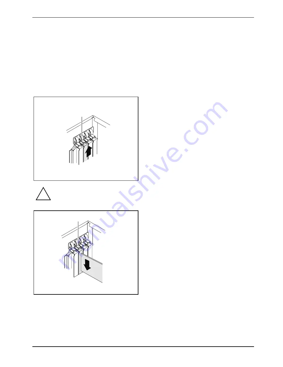
Installing an optional additional port
►
Open the casing (see "
X
Opening the casing
X
").
1
2
►
Press on the curved part of the retaining
clip (1).
►
Remove the rear slot cover plate from the
slot (2).
!
Do not dispose of the cover plate. For cooling, protection against fire and in order to
comply with EMC regulations, you must refit the cover plate if you later remove the port.
2
1
►
Push the port into the slot (1) as far as it will
go.
►
Press the port into the slot until you feel it
engage.
►
Press on the retaining clip until it you feel it
engage (2).
►
Connect the cable of the additional port to the connector on the mainboard.
►
Close the casing (see "
X
Closing the casing
X
").
Summary of Contents for ESPRIMO P5635
Page 1: ...ESPRIMO P5635 ESPRIMO P5730 ESPRIMO P7935 Operating Manual ...
Page 3: ......
Page 32: ...Operation 24 A26361 K1006 Z220 1 7619 edition 2 ...
Page 64: ...System upgrades 56 A26361 K1006 Z220 1 7619 edition 2 ...
Page 66: ...Technical data 58 A26361 K1006 Z220 1 7619 edition 2 ...
Page 70: ...Index 62 A26361 K1006 Z220 1 7619 edition 2 W Warm boot 20 Weight 57 ...


