Getting started
Connecting the device to the mains voltage
Device
Connecting
Device
►
Check the voltage setting.
2
1
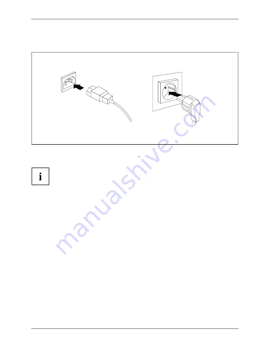
►
Connect the power cable to the device.
►
Plug the power plug into a properly grounded mains outlet.
The device is
fi
tted with a wide voltage range power supply. This means you
do not need to set the nominal voltage manually for these devices. Therefore
there is no switch available for the voltage setting.
Fujitsu
15
Summary of Contents for ESPRIMO C7 Series
Page 1: ...System Operating Manual ESPRIMO C7xx C9xx ...
Page 3: ......