background image

Add-on modules / Upgrading


20 

A26361-D1692-Z120-1-7619


Rear Audio Connectors 


Digital SPDIF COAX 
Digital interface Supports 5.1 Digital Surround Sound 


Analog Connectors 


Line in 


Line out (headphone capable) 


Microphone In 

Installing Add-In Cards 

Before installing add-in cards, you should ensure that they are fully compatible with your 
motherboard. If in doubt, check the specifications with the manufacturer.  
In order to illustrate the most common slots and what they support; we have provided the 
illustrations below. 


Simply find the appropriate slot for your add-in card and insert the card firmly.  
Never force any add-in cards into any slots if they do not seat in place. Doing so will damage the 
motherboard and void your warranty. 
*The AGP slot supports AGPPRO & 1.5v(4x/8x) AGP cards only 

Summary of Contents for D1692

Page 1: ...Technical Manual Mainboard D1692 English answers2 ...

Page 2: ...blems or other questions you need clarified Please contact your sales partner your sales outlet The latest information and updates e g BIOS update on our mainboards can be found on the Internet under http www fujitsu siemens com ...

Page 3: ......

Page 4: ... impreso sobre papel reciclado Questo manuale è stato stampato su carta da riciclaggio Denna handbok är tryckt på recyclingpapper Dit handboek werd op recycling papier gedrukt Herausgegeben von Published by Fujitsu Siemens Computers GmbH Bestell Nr Order No A26361 D1692 Z120 1 7619 Printed in the Federal Republic of Germany AG 1103 11 03 A26361 D1692 Z120 1 7619 ...

Page 5: ...Mainboard D1692 Technical Manual English November 2003 edition ...

Page 6: ......

Page 7: ...ark of Winbond Electronics Corporation All other trademarks referenced are trademarks or registered trademarks of their respective owners whose protected rights are acknowledged Copyright Fujitsu Siemens Computers GmbH 2003 All rights including rights of translation reproduction by printing copying or similar methods even of parts are reserved Offenders will be liable for damages All rights includ...

Page 8: ......

Page 9: ...1 INTR Chassis Intrusion Header J77 11 Front Panel Header J86 12 Gigabit Ethernet Disable J87 12 PCI X Slots 3 4 Bus Speed Override J92 12 SATA Serial ATA Controller Disable J112 12 RCV BIOS Recovery J7 12 BIOS Write Protect J8 13 USB D with Chipcardreader support J11 13 LCD header J45 13 Remote Temp J117 13 CPU and Chassis Fan Connectors 14 CPU and System Fan Specifications 14 Add on modules Upgr...

Page 10: ......

Page 11: ...formation which is important for your health or for preventing physical damage i indicates additional information which is required to use the system properly Ê Text which follows this symbol describes activities that must be performed in the order shown This symbol indicates that you must press the Enter key Text in this typeface indicates screen outputs Text in this bold typeface indicates the e...

Page 12: ...ions Information on which expansions you can use is available from your sales outlet or the customer service centre Information about boards To prevent damage to the mainboard the components and conductors on it please take great care when you insert or remove boards Take great care to ensure that extension boards are slotted in straight without damaging components or conductors on the mainboard o...

Page 13: ...l one header and one connector and one parallel port connector PS 2 KB mouse connectors Total six USB connections three rear connectors two front USB headers and one internal USB header with Chipcardreader support One LCD connector Expansion Slots One 8x AGP AGP PRO 110W slot 110W only with 550W power supply else AGP Pro 50W Four PCI X slots Two 64 bit 3 3v PCI X slots support up to 133 MHz on Bus...

Page 14: ...et Broadcom BCM5703C Gigabit Ethernet RJ 45 LAN connector with LEDs Connected to PCI X Bridge A 64 bit 100MHz Regulatory FCC Class B Declaration of Conformity European Community CE Declaration of Conformity BIOS Phoenix BIOS V4 06 on 4Mbit LPC Flash ROM ACPI 2 0 PXE via Ethernet USB device boot 48 bit LBA Support Form Factor SSI EEB v3 0 footprint 13 x 12 330 2x304 8 mm EPS12V SSI Workstation Spec...

Page 15: ...S12V SSI type power supplies 24pin 8pin 6pin and will not operate with any other types For proper power supply installation procedures see Installing the Power Supply section DO NOT USE ATX 2 x ATX12V or ATXGES power supplies as they will damage the board and void your warranty D1692 Block Diagram ...

Page 16: ...This diagram is representative of the latest board revision available at the time of publishing The board you receive may not look exactly like the above diagram Jumper Legend OPEN Jumper OFF without jumper cover CLOSED Jumper ON with jumper cover Key Pin Missing pin to indicate proper orientation ...

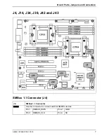
Page 17: ... and Connectors A26361 D1692 Z120 1 7619 7 J4 J14 J34 J39 J42 and J43 SMBus 1 1 Connector J4 J4 SMBus 1 1 Connector Use this connector to connect external SMBUS devices Pin 1 SMBUS_DATA Pin 2 GND Pin 3 SMBUS_CLK Pin 4 NC ...

Page 18: ...n2 and Pin3 for several seconds to Clear CMOS Put jumper cap back to Pin1 and Pin2 default setting Reconnect power power on system NOTE If you do not disconnect the power connectors from the motherboard the CMOS may not clear completely PCI X Slots 3 4 Force PCI Mode Jumper J39 J39 PCI X Slots 3 4 Force PCI Mode Jumper Open Default Allows PCI 3 4 to operate in PCI X mode Closed Force PCI slots 3 4...

Page 19: ...pers on Pin 5 6 and Pin 9 10 to get audio or microphone signals on your front or rear audio connections Signal Pin Pin Signal MIC In FP 1 2 Audio GND MIC BIAS 3 4 Audio Analog Right Front out 5 6 Right Rear In No Connect 7 8 Key Left Front Out 9 10 Left Rear In WARNING Do not place jumpers on this header in any other configuration Doing so could result in damage to the motherboard ...

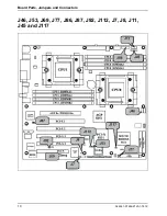
Page 20: ...Board Parts Jumpers and Connectors 10 A26361 D1692 Z120 1 7619 J46 J53 J69 J77 J86 J87 J92 J112 J7 J8 J11 J45 and J117 ...

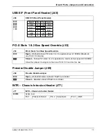
Page 21: ...fault Allows PCI slots 1 2 to operate at up to 133MHz Maximum one PCI X 133 device Closed Forces PCI slots 1 2 to operate at a maximum bus speed of 100 MHz Close this jumper if using more than one PCI X 133 card on this bus Firewire Disable Jumper J69 J69 Firewire Disable Jumper Open Default Enables onboard FireWire controller Closed Disables onboard FireWire controller INTR Chassis Intrusion Head...

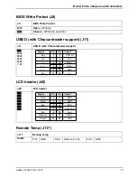
Page 22: ...peed Override J92 J92 PCI X Slots 3 4 Bus Speed Override Open Default Allows PCI 3 4 to operate at up to 100MHz Closed Force PCI slots 3 4 to operate in at a maximum 66MHz Note This jumper affects integrated Ethernet on the same bus SATA Serial ATA Controller Disable J112 J112 SATA Serial ATA Controller Disable Open Default Enable onboard SATA Controller Closed Disable onboard SATA Controller RCV ...

Page 23: ...rt J11 J11 USB D with Chipcardreader support Signal Pin Pin Signal Key 1 2 CCR on n c 3 4 VCC n c 5 6 Data n c 7 8 Data n c 9 10 GND Key 11 12 n c LCD header J45 J45 LCD header Signal Pin Pin Signal Clock 1 2 GND Data 3 4 GND Key 5 6 RFU LAN Action 7 8 LAN Link IDE 9 10 Alert Message 11 12 Sleep Power 13 14 VDD Remote Temp J117 J117 Remote Temp Pin1 GND Pin2 Remote_Temp Pin3 GND ...

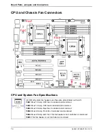
Page 24: ...the same pinout listed on the left FAN1 Max 1 2 Amp CPU fan Controlled and monitored FAN2 Max 1 2 Amp CPU fan Controlled and monitored FAN3 Max 3 0 Amp Rear fan Controlled and monitored FAN6 Max 2 0 Amp Front fan Controlled and monitored FAN4 Max 2 0 Amp AUX fan This fan header is not controlled or monitored FAN5 This fan header is not controlled or monitored ...

Page 25: ...age as a result of operating an unsupported configuration The diagram is provided as a visual guide to help you install socket processors and may not be an exact representation of the processors you have Lift the lever on the socket until it is approximately 90o or as far back as possible to the socket Align the processor with the socket There are keyed pins underneath the processor to ensure that...

Page 26: ...e plastic retention brackets After you have finished installing the heat sink onto the processor and socket attach the end wire of the fan which should already be attached to the heat sink to the motherboard The diagram illustrates how to connect fans onto the motherboard Installing the Memory Before attempting to install any memory make sure that the memory you have is compatible with the motherb...

Page 27: ...ower on self test 128MB 256MB 512MB 1GB and 2GB Registered PC2700 PC2100 PC1600 DDR SDRAM memory modules are supported All installed memory will be automatically detected The mainboard D1692 supports up to 8GB with two CPUs installed Use only identical DIMMs for one channel Memory must be installed in pairs of DIMMs CPU0 DIMMA1 and CPU0 DIMMA2 CPU0 DIMMB1 and CPU0 DIMMB2 CPU1 DIMMA1 and CPU1 DIMMA...

Page 28: ...S unplug the power connector from the motherboard before performing system hardware changes Otherwise you may damage the board and or expansion device Attaching Drive Cables Attaching the IDE drive cable is simple These cables are keyed to only allow them to be connected in the correct manner The mainboard D1692 has two on board IDE channels each supporting two drives The black connector designate...

Page 29: ...ictures illustrate how to connect an SATA drive 1 SATA drive cable connection 2 SATA drive power connection 3 SATA cable motherboard connector 4 SATA drive power adapter Floppy Drives Attaching floppy diskette drives are done in a similar manner to hard drives In most cases there will be a key pin on the cable which will force a proper connection of the cable Attach floppy drive drive A to the end...

Page 30: ... that they are fully compatible with your motherboard If in doubt check the specifications with the manufacturer In order to illustrate the most common slots and what they support we have provided the illustrations below Simply find the appropriate slot for your add in card and insert the card firmly Never force any add in cards into any slots if they do not seat in place Doing so will damage the ...

Page 31: ... or devices also use this line this means the line is shared According to the PCI specification all cards and devices must support interrupt sharing Some cards however might cause instabilities or performance degradation if they share an interrupt Try moving those cards to a slot where they won t share an interrupt Some cards may use more than one interrupt For these cards also take into considera...

Page 32: ... the 8 pin power connector into the 6 pin motherboard connector Doing so will damage the motherboard and or other components Please be aware that ATX 2 x and ATXGES power supplies are not compatible with the board and can damage the motherboard and or CPU s Disconnect power supply from electrical outlet Connect the EPS12V 8 pin power connector Connect the SSI Workstation 6 pin power connector if n...

Page 33: ...lithium battery may be replaced only with an identical battery or with a type recommended by the manufacturer Do not throw lithium batteries into the household waste They must be disposed of in accordance with local regulations concerning special waste Ensure that you insert the battery the right way round The plus pole must be on the top The lithium battery holder exists in different designs that...

Page 34: ...the drive Restart the PC Follow the instructions on screen BIOS Recovery i All BIOS settings are reset to the default values Opening the casing as described in the operating manual Close the jumper RCV J7 Close the casing as described in the operating manual Insert a BIOS Recovery Disk and start the PC Note the signals issued from the buzzer or loudspeaker You have successfully restored the BIOS i...

Page 35: ...rea Network RAMDAC Random Access Memory Digital Analogue Converter CPU Central Processing Unit RDRAM Rambus Dynamic Random Access Memory CNR Communication Network Riser RIMM Rambus Inline Memory Module C RIMM Continuity Rambus Inline Memory Module RTC Real Time Clock DIMM Dual Inline Memory Module SB Soundblaster ECC Error Correcting Code SDRAM Synchronous Dynamic Random Access Memory EEPROM Elect...

Reviews: