


En-2
Precautions for using R32 refrigerant
The basic installation work procedures are the same as conventional refrigerant (R410A,
R22) models.
However, pay careful attention to the following points:
Since the working pressure is 1.6 times higher than that of refrigerant R22 models,
some of the piping and installation and service tools are special. (Refer to “2. 1. Instal-
lation tools”.)
Especially, when replacing a refrigerant R22 model with a new refrigerant R32 model,
always replace the conventional piping and flare nuts with the R32 and R410A piping and
fl
are nuts on the outdoor unit side.
For R32 and R410A, the same
fl
are nut on the outdoor unit side and pipe can be used.
Models that use refrigerant R32 and R410A have a different charging port thread diam-
eter to prevent erroneous charging with refrigerant R22 and for safety. Therefore, check
beforehand. [The charging port thread diameter for R32 and R410A is 1/2-20 UNF.]
Be more careful than R22 so that foreign matter (oil, water, etc.) does not enter the
piping. Also, when storing the piping, securely seal the opening by pinching, taping, etc.
(Handling of R32 is similar to R410A.)
CAUTION
1-Installation (Space)
• That the installation of pipe-work shall be kept to a minimum.
• That pipe-work shall be protected from physical damage.
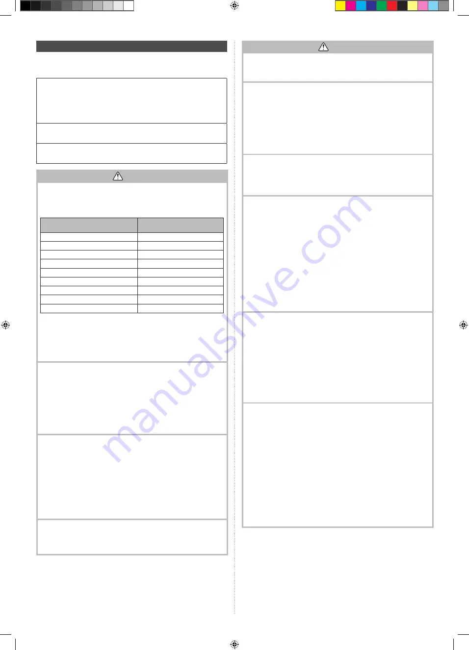
• The appliance shall not be installed in an unventilated space, if that space is smaller
than X m².
Amount of refrigerant charge
M (kg)
Minimum room area
X (m
2
)
M
≤
1.22
-
1.22 < M
≤
1.23
1.45
1.23 < M
≤
1.50
2.15
1.50 < M
≤
1.75
2.92
1.75 < M
≤
2.0
3.82
2.0 < M
≤
2.5
5.96
2.5 < M
≤
3.0
8.59
3.0 < M
≤
3.5
11.68
3.5 < M
≤
4.0
15.26
(IEC 60335-2-40)
• That compliance with national gas regulations shall be observed.
• That mechanical connections shall be accessible for maintenance purposes.
• In cases that require mechanical ventilation, ventilation openings shall be kept clear
of obstruction.
• When disposing of the product is used, be based on national regulations, properly
processed.
2-Servicing
2-1 Service personnel
• Any person who is involved with working on or breaking into a refrigerant circuit
should hold a current valid certi
fi
cate from an industry-accredited assessment
authority, which authorises their competence to handle refrigerants safely in accor-
dance with an industry recognised assessment speci
fi
cation.
• Servicing shall only be performed as recommended by the equipment manufacturer.
Maintenance and repair requiring the assistance of other skilled personnel shall be
carried out under the supervision of the person competent in the use of
fl
ammable
refrigerants.
• Servicing shall be performed only as recommended by the manufacturer.
2-2 Work
• Prior to beginning work on systems containing
fl
ammable refrigerants, safety checks
are necessary to ensure that the risk of ignition is minimized. For repair to the refrig-
erating system, the precautions in 2-2 to 2-8 shall be complied with prior to conduct-
ing work on the system.
• Work shall be undertaken under a controlled procedure so as to minimize the risk of
a
fl
ammable gas or vapour being present while the work is being performed.
• All maintenance staff and others working in the local area shall be instructed on the
nature of work being carried out.
• Work in con
fi
ned spaces shall be avoided.
• The area around the workspace shall be sectioned off.
• Ensure that the conditions within the area have been made safe by control of
fl
am-
mable material.
2-3 Checking for presence of refrigerant
• The area shall be checked with an appropriate refrigerant detector prior to and during
work, to ensure the technician is aware of potentially
fl
ammable atmospheres.
• Ensure that the leak detection equipment being used is suitable for use with
fl
am-
mable refrigerants, i.e. nonsparking, adequately sealed or intrinsically safe.
CAUTION
2-4 Presence of
fi
re extinguisher
• If any hot work is to be conducted on the refrigeration equipment or any associated
parts, appropriate
fi
re extinguishing equipment shall be available at hand.
• Have a dry powder or CO
2
fi
re extinguisher adjacent to the charging area.
2-5 No ignition sources
• No person carrying out work in relation to a refrigeration system which involves
exposing any pipe work that contains or has contained
fl
ammable refrigerant shall
use any sources of ignition in such a manner that it may lead to the risk of
fi
re or
explosion.
• All possible ignition sources, including cigarette smoking, should be kept suf
fi
ciently
far away from the site of installation, repairing, removing and disposal, during which
fl
ammable refrigerant can possibly be released to the surrounding space.
• Prior to work taking place, the area around the equipment is to be surveyed to make
sure that there are no
fl
ammable hazards or ignition risks. “No Smoking” signs shall
be displayed.
2-6 Ventilated area
• Ensure that the area is in the open or that it is adequately ventilated before breaking
into the system or conducting any hot work.
• A degree of ventilation shall continue during the period that the work is carried out.
• The ventilation should safely disperse any released refrigerant and preferably expel
it externally into the atmosphere.
2-7 Checks to the refrigeration equipment
• Where electrical components are being changed, they shall be
fi
t for the purpose
and to the correct speci
fi
cation.
• At all times the manufacturer’s maintenance and service guidelines shall be followed.
• If in doubt consult the manufacturer’s technical department for assistance.
• The following checks shall be applied to installations using
fl
ammable refrigerants.
- The charge size is in accordance with the room size within which the refrigerant
containing parts are installed.
- The ventilation machinery and outlets are operating adequately and are not
obstructed.
- If an indirect refrigerating circuit is being used, the secondary circuit shall be
checked for the presence of refrigerant.
- Marking to the equipment continues to be visible and legible. Markings and signs
that are illegible shall be corrected.
- Refrigeration pipe or components are installed in a position where they are unlikely
to be exposed to any substance which may corrode refrigerant containing compo-
nents, unless the components are constructed of materials which are inherently
resistant to being corroded or are suitably protected against being so corroded.
2-8 Checks to electrical devices
• Repair and maintenance to electrical components shall include initial safety checks
and component inspection procedures.
• If a fault exists that could compromise safety, then no electrical supply shall be con-
nected to the circuit until it is satisfactorily dealt with.
• If the fault cannot be corrected immediately but it is necessary to continue operation,
an adequate temporary solution shall be used.
• This shall be reported to the owner of the equipment so all parties are advised.
• Initial safety checks shall include.
- That capacitors are discharged: this shall be done in a safe manner to avoid pos-
sibility of sparking.
- That there no live electrical components and wiring are exposed while charging,
recovering or purging the system.
- That there is continuity of earth bonding.
3-Repairs to sealed components
• During repairs to sealed components, all electrical supplies shall be disconnected
from the equipment being worked upon prior to any removal of sealed covers, etc.
• If it is absolutely necessary to have an electrical supply to equipment during servic-
ing, then a permanently operating form of leak detection shall be located at the most
critical point to warn of a potentially hazardous situation.
• Particular attention shall be paid to the following to ensure that by working on electri-
cal components, the casing is not altered in such a way that the level of protection is
affected.
• This shall include damage to cables, excessive number of connections, terminals not
made to original speci
fi
cation, damage to seals, incorrect
fi
tting of glands, etc.
• Ensure that apparatus is mounted securely.
• Ensure that seals or sealing materials have not degraded such that they no longer
serve the purpose of preventing the ingress of
fl
ammable atmospheres.
• Replacement parts shall be in accordance with the manufacturer’s speci
fi
cations.
NOTES: The use of silicon sealant may inhibit the effectiveness of some types of leak
detection equipment.
Intrinsically safe components do not have to be isolated prior to working on
them.
381798070_IM.indb 2
381798070_IM.indb 2
12/5/2018 9:39:31 AM
12/5/2018 9:39:31 AM


