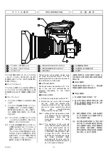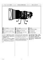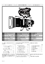
RD-S45T
-
2 -
レ
ン
ズ
の
概
要
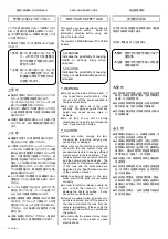
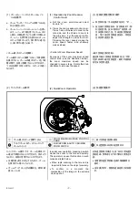
このレンズは、カラーテレビカメラ用に開発さ
れた、バヨネットマウントタイプのズームレン
ズです。
カ
メ
ラ
へ
の
取
り
付
け
注
.
レンズをカメラに取り付ける前に、必ずカ
メラの電源を
OFF
にしてください。
警
告
取り付け・締め付けは確実に行ってくださ
い。高所使用時の落下は重大な事故の
原因となります。
a.
後レンズキャップを外します。
b.
カメラのマウントクランプリングを、反時
計方向一杯に回します。
c.
レンズのマウント面にあるピンが、カメラ
のマウント面にある穴、または切り欠きに
確実に入るように位置を合わせてから、
レンズとカメラのマウント面を合わせま
す。
d.
マウントクランプリングを時計方向一杯に
回します。
e.
レンズのケーブルをカメラのレンズ用コネ
クタに接続します。
注
.
レンズを最初にカメラに取り付けたとき、
または異なるカメラに取り付けたときには、
必ずフランジバックの調整(次ページ参
照)を行ってください。
GENERAL DESCRIPTION
This lens is a bayonet mount type zoom
lens developed for a color TV Camera.
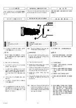
INSTALLATION ONTO CAMERA
Note. Prior to installation of the lens, turn
off the power of the camera.
WARNING
Be sure to attach all the parts securely.
Dropping any parts from a height may
cause severe accidents.
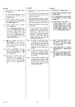
a. Take the rear lens cap off.
b. Rotate the mount clamp ring on the
camera fully counterclockwise.
c. Fit the mounting surface of the lens to
that of the camera aligning the pin on
the lens with the slot in the camera.
d. Rotate the mount clamp ring fully
clockwise.
e. Connect the cable of the lens to the
connector, provided for the lens, on
the camera.
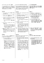
Note. Make sure to adjust the flange focal
length when installing the lens on a
camera for the first time or installing
it on another camera (refer to the
next page for details).
一 般 说 明
本镜头是为摄录一体机研发的卡口安装式
变焦镜头。
连 接 摄 像 机
注:安装镜头之前,应关闭摄像机电源。
警
告
务必将所有部件稳固连接。在高处使用
时
,
部件的坠落,可能会导致严重事故。
a.
打开后组镜头盖。
b.
向逆时针(从镜头正面看)方向充分转
动摄像机连接卡环。
c.
将镜头卡口表面和摄像机安装面贴合在
一起,并将镜头上的定位梢对准摄像机
上的槽。
d.
向顺时针方向充分转动连接卡环。
e.
将镜头电缆连接到摄像机上的镜连接
器。
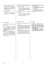
注:首次在摄像机上安装镜头或在不同的摄
像机上安装镜头时,请务必进行镜座距
调节(请参阅下一页)。如果没有正确
调节镜头与摄像机之间的镜座距,在调
焦时可能无法对焦,从而给拍摄带来很
大的不便。而且也无法发挥镜头最基本
的光学性能作用。
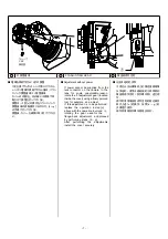
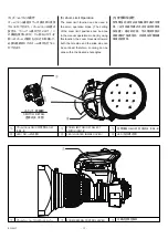
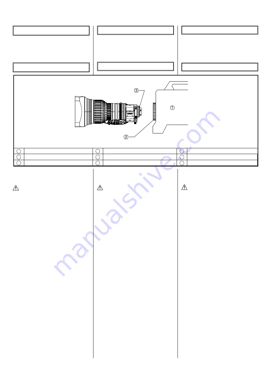
1
カメラ
1
CAMERA
1
摄像机
2
マウントクランプリング
2
MOUNT CLAMP RING
2
支座夹环
3
ピン
3
PIN
3
锁栓
Summary of Contents for Fujinon UA22x8BERD-S8
Page 1: ...H BB00031483 101 LP750A S8 2804 UA22 8BERD S8...
Page 2: ......
Page 5: ...10 SJ T11364 GB T26572 GB T26572...
Page 37: ...ILLUSTRATIONS...
Page 38: ......
Page 39: ...MEMO...
Page 41: ...mm UNLESS OTHERWISE SPECIFIED UNIT mm Outline drawing UA22 X 8BERD S8 Fig 1 1 GLP750AS800 11...
Page 42: ......
Page 43: ...Drive unit wiring diagram Fig 2 2 AMPLIFIER AMPLIFIER P C B P C B SS00001799 00...
Page 44: ......
Page 45: ...SIEMENS STAR CUT LINE...
Page 46: ......
Page 48: ......


