


Service Manual for FNDX 5
08/2009 FR
Page 14
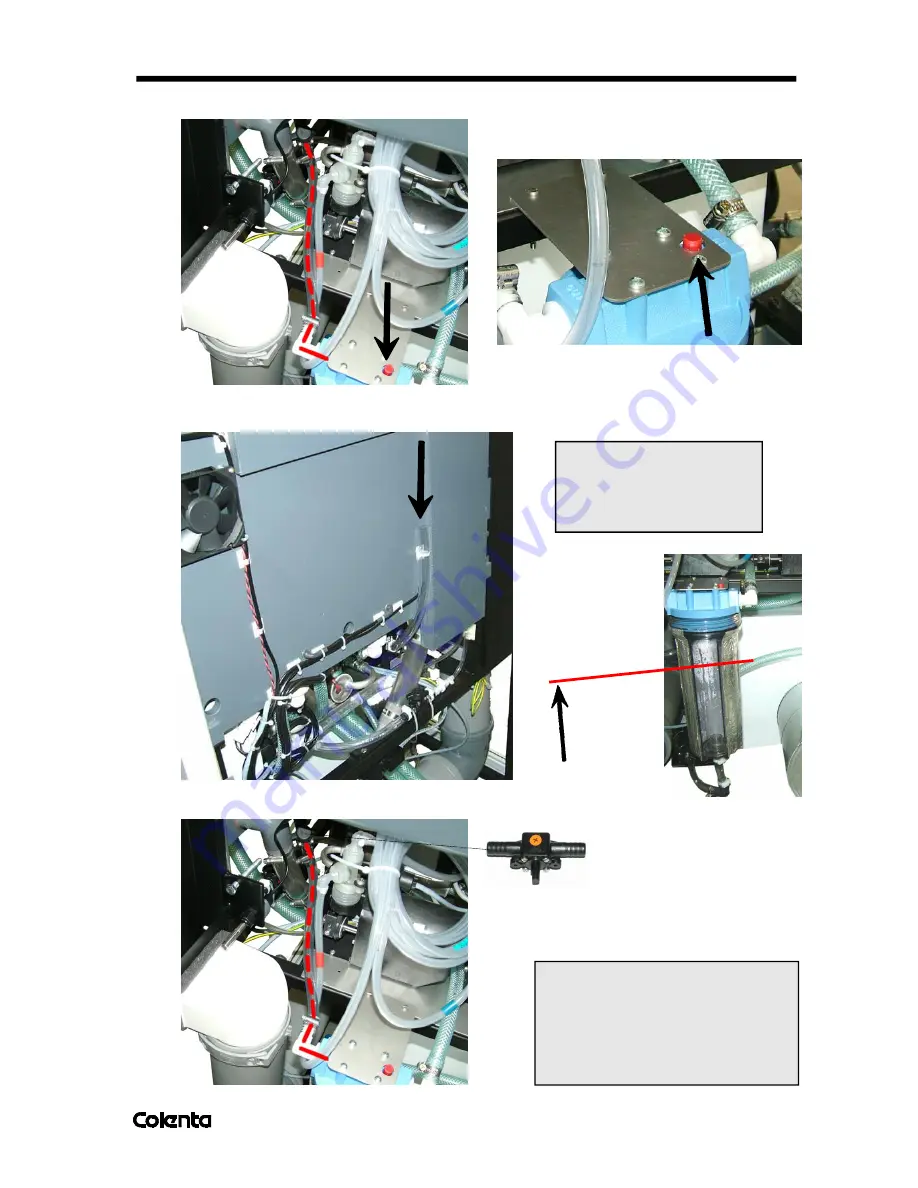
3.
Press the red button all the time during the filling!
4.
Fill in Cooling Liquid carefully up to 3/4 of the Filter using a funnel, while pressing the red button!
CAUTION:
Do not fill in more than
up to 3/4
of the
Cooling Liquid Tank!
5.
Close the marked Stop cock to the Chiller Assy
Fill in up to 3
/4
(about 2 litre
s)
IMPORTANT:
After the first cooling cyclus, control
the level of the cooling liquid.
Contingently fill up the cooling liquid
to the right level.
Inspection glass should filled 3/4.