background image

94

7. Appendix

FinePix S5100/S5500 Service Manual

7. Appendix

7-1. Function of  display for Firmware Version

The function to display the version is installed in FinePix
S5100.
The version the camera equipped with of the firmware can be
displayed only by operating the main body of the camera.

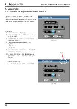
[Procedure]

1. The camera is made a play mode.

2. The power supply switch is turned on while pressing

the shutter button.

3. The "SETUP" display is selected, and changes to a

DATE/TIME  set mode.

4. The DATE/TIME setting is matched as follows

(Fig. 7-1).

• 2040 .  2.  29

• 11  : 59   PM

5. After the date is set,  keeps pressing the shutter button

for three seconds or more.

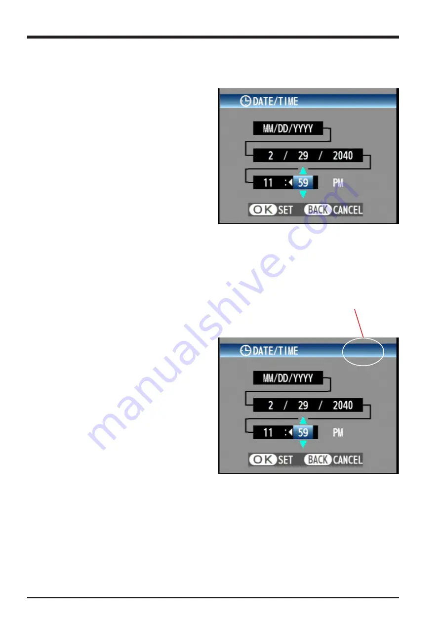
6. The version of the farmware is displayed in the upper

right of LCD only while the shutter button is being done
(Fig. 7-2).

Example of display: 1.28

* It is shown that the version of the farm-ware is 1.28.

<Fig. 7-1>

<Fig. 7-2>

Version

1.28

Summary of Contents for FinePix S5100

Page 1: ...REPLACE ONLY BY THE COMPONENTS SPECIFIED ON THE SCHEMATIC DIAGRAM AND IN THE PARTS LIST IF YOU USE PARTS NOT SPECIFIED IT MAY RESULT IN A FIRE AND AN ELECTRICAL SHOCK FUJI PHOTO FILM CO LTD Ref No ZM00574 102 Printed in Japan 2005 11 DIGITAL CAMERA FinePix S5100 S5500 US CA EU EG GE AS CH Model SERVICE MANUAL WARNING ...

Page 2: ...oldered connections Check the entire board surface for solder splasher and bridges 2 Check the interboard wiring to ensure that no wires are pinched or contact high wattage resistors 3 Look for unauthorized replacement parts particularly transistors that were installed during a previous repair Point them out to the customer and recommend their replacement 4 Look for parts which though functioning ...

Page 3: ...s 42 4 2 Measuring Instruments Used 42 4 3 Use Jig list 42 4 4 Calibration method of pattern box 43 4 5 Adjusting soft installation 43 4 5 1 Various downloading software decompressions preservation methods and notes 43 4 5 2 Installation of DSC jig driver 44 4 5 3 Adjusting soft initiation method 44 4 6 Initial Settings of the Adjustment Software 45 4 7 Starting the Adjustment Software 48 4 8 R Fl...

Page 4: ...UTO Equivalent to ISO 64 to 320 depending on coditions 64 100 200 400 P S A M Equivalent to ISO 64 100 200 400 During setting CCD RAW ISO 64 100 200 Photometry TTL 64 zones metering Multi Spot Average Exposure control Program AE P Shutter priority AE Aperture priority AE Manual exposure Exposure compensation 2 0 EV to 2 0 EV in 1 3 EV step increments in Programmed auto shutter priority auto Apertu...

Page 5: ...0 oz not including accessories batteries and xD Picture Card Weight for photography Approx 480 g 16 9 oz including batteries and xD Picture Card Accessories z AA size alkaline batteries LR6 4 z 16 MB xD Picture Card 1 Included with Anti static case 1 z Shoulder strap 1 z A V cable for FinePix S5100 FinePix S5500 1 approx 1 5 m 4 9 ft plug 2 5 mm dia to pin plug 2 z USB cable mini B 1 z Adapter rin...

Page 6: ...t the difference between standard number of frames and the actual number of frames is greater for xD Picture Cards with higher capacities Quality Setting Number of recorded pixels DPC 16 16 MB 1600 1200 25 640 480 122 2272 1704 1 50 247 3 101 497 7 204 997 15 F 2272 1704 8 16 33 66 134 268 N 16 32 66 132 266 532 409 818 1280 960 33 68 137 275 550 1101 1997 3993 30 61 Movie 640 480 13 sec Image Dat...

Page 7: ...e EV increases by 1 Likewise when the light is halved the EV decreases by 1 Frame rate fps The frame rate refers to the number of images frames that are photographed or played back per second For example when 10 frames are continuously photographed in a 1 second interval the frame rate is expressed as 10 fps For reference TV images are displayed at 30 fps NTSC JPEG Joint Photographics Experts Grou...

Page 8: ...Focus mode selector lock switch W Wide zoom button Photo mode button DISP display BACK button Low light viewfinder button Battery cover MENU OK button 4 direction button T Tele zoom button Strap mount Viewfinder EVF Diopter adjustment dial EVF LCD monitor selector button Tripod mount LCD monitor Indicator lamp Macro button Flash button 1 3 Names of External Components ...

Page 9: ... Manual Flash pop up button Strap mount Slot cover USB socket mini B DC IN 5V power input socket A V OUT Audio Visual output socket Self timer lamp Microphone Flash Flash control sensor AF Assist illuminator Speaker xD Picture Card slot Lens ...

Page 10: ...embly 2 1 Names of internal Components CABI REAR ASSY LCD ASSY LENS CONST MAIN PWB ASSY CABI FRONT ASSY BATTERY HOLDER ASSY STROBE CONST MIC ASSY SPEAKER ASSY EVF UNIT CONST RSW PWB ASSY MAIN FRAME DCST PWB ASSY LCD FRAME AF FRAME ASSY KSW PWB ASSY MSW PWB ASSY ...

Page 11: ...ly 1 Remove the three screws M1 7 x 3 5 2 Remove the two screws M1 7 x 5 3 Open the battery cover 4 Raise the CABI REAR ASSY in the direction of the arrow 1 1 2 3 4 5 Remove the FFC Assembly Set the mode dial to the camera position and assemble it Assemble in the reverse order to disassembly 5 ...

Page 12: ...00 S5500 Service Manual 2 3 Removing the LCD ASSY Disassembly 1 Remove the two screws M1 7 x 2 5 3 Raise the LCD ASSY in the direction of the arrow Assembly Assemble in the reverse order to disassembly 1 2 3 2 Remove the connector ...

Page 13: ...ove the connector 2 Remove the three FFCs 3 Raise the NAIN PWB in the direction of the arrow 1 2 2 3 2 4 Removing the EVF UNIT CONST Disassembly 1 Remove the connector 2 Raise the EVF UNIT CONST in the direction of the arrow 3 Remove the FFC Assembly Assemble in the reverse order to disassembly 1 2 3 ...

Page 14: ...14 2 Disassembly FinePix S5100 S5500 Service Manual 4 Assembly Make the style of FFC and the lead wire as shown in figure below 4 Remove the FFC ...

Page 15: ...sembly 1 Remove the connector 2 Remove the screw M1 7 x 8 0 3 Remove the BATTERY HOLDER ASSY in the direction of the arrow 1 2 3 Assembly Set the switch lever to the off position when assembling OFF Note Always ensure that the FLASH ASSY main condenser is discharged before beginning disassembly ...

Page 16: ...onnectors 4 Remove the DCST PWB ASSY in the direction of the arrow 1 2 3 4 Assembly Put the substrate aside in the direction of the arrow when assembling 2 8 Removing the LENS CONST Disassembly 1 Remove the three screws M1 7 x 8 0 2 Remove the MAIN FRAME 3 Remove the LENS CONST in the direction of the arrow Assembly Assemble in the reverse order to disassembly 1 2 3 ...

Page 17: ...e STROBE CONST Disassembly 1 Remove the ST BUTTON 1 2 3 4 2 Remove the screw M1 7 x 5 5 3 Remove the connector 4 Remove in the STROBE CONST direction of the arrow Assembly Make read wire a style as shown in the figure below Assemble in the reverse order to disassembly ...

Page 18: ...ePix S5100 S5500 Service Manual 1 2 2 10 Removing the AF FRAME ASSY Disassembly 1 Remove two screws 2 Remove the AF FRAME ASSY in the direction of the arrow Assembly Execute the AF Assist Light Adjustment after assembling ...

Page 19: ...layed 3 2 Basic Block Names and Functions Part name Block name Function LENS CONST CCD FPC BLOCK CCD output IC701 MAIN PWBASSY CAM BLOCK CCD output A D conversion IC103 CCD driver IC101 IC102 PROCESS BLOCK Image signal processing USB communications system control IC201 Image signal processing assist IC202 LCD EVF BLOCK LCD EVF output control IC401 VIDEO BLOCK VIDEO output IC51 AUDIO BLOCK Audio IN...

Page 20: ...duction processing linear matrix processing gamma correction and R G B 14 bit to R G B 8 bit conversion to 8 bit digital R G B signals to Y Cb Cr 4 2 2 YC processing are implemented in this signal processing section and 8 bit Y Cb Cr image data are sent to the internal buffer Noise reduction processing linear matrix processing and gamma correction included here are processed by the Partner chip Th...

Page 21: ...V Jack SIO1 U2_SO U2_SCK SIO1 U2_SCK U2_SO 10xZOOM LENS f 5 7 57 0mm F 2 8 3 1 O LPF CCD IC701 IC103 IC101 IC651 IC102 ICX448DQ 1 2 7inch 4 0millon pixels USB Jack xD Card STRB XE DC IN 5V BATT AA x 4 P TR BATT Backup DC DC Block DC DC IC AN30212A 5ch 1 5V 3 3V 5V CCD 15V 7 5V LCD Etc PW_CTR 3 3V_ON LED_R LED_G IPS AN30203AA STROBOCTRL LED DRIVER x 3 RTC Power on Reset CTL FUSE 32 768kHZ LED_ST Pa...

Page 22: ...6 67 68 69 70 51 52 53 54 55 56 57 58 60 59 61 62 63 64 65 66 67 68 70 69 D_3 3V EV3 GND D_3 3V GND D3 3V CAM_3 3V AU_3 3V CAM_3 3V AU_3 3V CCD_15V GND CCD_15V GND GND D_1 5V GND D_1 5V CCD_ 7 5V D_1 5V CCD_ 7 5V D_5 2V D_3 4V GND D_3 4V GND CCD_ON SHT_CLS NC 3 3V_ON SHT_OPN LED_ST MOT_RESET LED_G Z_HP LED_R F_HP GND MOT_CS GND MOT_CLK PW_SW MOT_MOB_Z BAT_V MOT_MOB_F PWR_SW MOT_MOB_I IPS_CS GND IP...

Page 23: ...23 3 Schematics FinePix S5100 S5500 Service Manual 3 6 Circuit Diagrams 3 6 1 CAM BLOCK ...

Page 24: ...24 3 Schematics FinePix S5100 S5500 Service Manual 3 6 2 DCDC BLOCK ...

Page 25: ...25 3 Schematics FinePix S5100 S5500 Service Manual 3 6 3 KSW BLOCK ...

Page 26: ...26 3 Schematics FinePix S5100 S5500 Service Manual 3 6 4 LCD EVF BLOCK ...

Page 27: ...27 3 Schematics FinePix S5100 S5500 Service Manual 3 6 5 MOTOR BLOCK ...

Page 28: ...28 3 Schematics FinePix S5100 S5500 Service Manual 3 6 6 PROCESS BLOCK ...

Page 29: ...29 3 Schematics FinePix S5100 S5500 Service Manual 3 6 7 CCD FPC BLOCK ...

Page 30: ...30 3 Schematics FinePix S5100 S5500 Service Manual 3 6 8 IPS STROBE BLOCK ...

Page 31: ...31 3 Schematics FinePix S5100 S5500 Service Manual 3 6 9 MSW BLOCK 3 6 10 RSW BLOCK ...

Page 32: ...32 3 Schematics FinePix S5100 S5500 Service Manual 3 7 Mounted Parts Diagrams 3 7 1 DCST PWB ASSY SIDE A ...

Page 33: ...33 3 Schematics FinePix S5100 S5500 Service Manual SIDE B ...

Page 34: ...34 3 Schematics FinePix S5100 S5500 Service Manual 3 7 2 MAIN PWB ASSY SIDE A ...

Page 35: ...35 3 Schematics FinePix S5100 S5500 Service Manual SIDE B ...

Page 36: ...36 3 Schematics FinePix S5100 S5500 Service Manual 3 7 3 KSW FPC ASSY SIDE A ...

Page 37: ...37 3 Schematics FinePix S5100 S5500 Service Manual SIDE B ...

Page 38: ...38 3 Schematics FinePix S5100 S5500 Service Manual 3 7 4 MSW FPC ASSY SIDE A ...

Page 39: ...39 3 Schematics FinePix S5100 S5500 Service Manual SIDE B ...

Page 40: ...40 3 Schematics FinePix S5100 S5500 Service Manual 3 7 5 RSW FPC ASSY SIDE A SIDE B ...

Page 41: ...41 3 Schematics FinePix S5100 S5500 Service Manual SIDE A SIDE B 3 7 6 CCD FPC ASSY ...

Page 42: ...PixM603 ZJ00653 100 LB140 filter holder kit for X Y stage General adjustment Common with the FinePixF610 ZJ00650 100 VIDEO adjustment jig Video adjustment Common with the FinePixA310 ZJ00553 100 AF solid chart General adjustment Common with the FinePixS2Pro FZ03983 100 AC Cable For EG Use with VIDEO adjustment jig Common with the FinePixA310 2 FZ03982 100 AC Cable For EU Use with VIDEO adjustment ...

Page 43: ...ompression of ZIP form files Therefore after downloading these compression files from the Web server the decompression of the file is necessary In the decompression software if the decompression of the ZIP form can be done any software is OK Please prepare each one for the decompression software The decompression and the preservation method of the PC adjustment software and the firmware are descri...

Page 44: ...uter in order to start the PC adjustment software the DSC jig driver needs to be installed in the personal computer beforehand The DSC jig driver is the same as that for the FinePix S7000 so if this jig driver software is already installed in the personal computer it is not necessary to install it The procedure is given below Step 1 DSC jig driver ZJ00684 100 ZIP is downloaded from Web server http...

Page 45: ...f the program is rewritten the adjustment software will not startup Step 1 Double click on the FFW exe execute file of the adjustment software to open the FFW Startup screen Fig 4 6 1 Step 2 Click on Settings 1 in Fig 4 6 2 in the menubar of the startup window Then select Mode setting 2 in Fig 4 6 2 from the pull down menu that appears Fig 4 6 2 1 2 FinePix S5100 5500_W Adjustment Software Start u...

Page 46: ... Step 5 Select the Hardware tab 1 in Fig 4 6 5 in the Customize dialog box that appears Input the values for PI and P Board 2 in Fig 4 6 5 PIO 0 10 12 14 16 PIO 1 11 13 15 17 Set the Hardware items 3 in Fig 4 6 5 as follows Item Details Debug Mode Select Default Step 6 Once the above settings have been made click on Apply 4 in Fig 4 6 5 in the Customize dialog box to complete setup This applies th...

Page 47: ...for Auto Adjust in user program Help Help Basic software help FF help User program help Focus Not used with this adjustment software Version Version information for basic software Table FFW exe Commands Cautions When Adjusting 1 FinePix S5100 S5500 cannot adjust the EVR data reading and writing Details are right tables 2 End Setting returns the camera from the Jig mode to the Product Mode End Sett...

Page 48: ...is adjustment software 4 Proceed with adjustment after reading the cautions here and the relevant cautions noted in the Service Manual Press the Enter key to proceed to the Jig Mode Setup screen Fig 4 7 2 FinePix S5100 5500_W Adjustment Software Start up Screen Select Start from Operate on the FFW Toolbar The adjustment software starts Fig 4 7 1 4 7 Starting the Adjustment Software Step 1 Double c...

Page 49: ... 2 Connect the Power Cable Jig with the camera 3 Adjust the output current of the power supply to 3 0A or less 4 Adjust the output voltage of the power supply to 5 0 0 02V 5 Connect the USB cable with the camera and PC 6 Switch ON the camera power while pressing the shutter button 7 Check that the LED at the under the viewfinder is lights in green Press the Enter key after completing the procedure...

Page 50: ...of the screen indicates the version number of the adjustment software 2 After running firmware download other adjustments may be required depending on the content of the download software In such cases the items to be adjusted and the sequence of adjustment will be indicated separately 3 After starting the adjustment software and beginning communication with the camera always run End Setting follo...

Page 51: ...ssful completion of the adjustments In some cases the camera may be completely disabled If this occurs set the camera to jig mode again and then reset the flash memory Step 1 In the adjustment item selection screen select R Reset flash memory The flash memory reset confirmation screen appears The Reconfirm flash memory reset screen then appears Flash memory reset EVR Attention When the MAIN PWB AS...

Page 52: ... MAIN PWB ASSY has not been replaced all the adjusted data reverts to the default settings In this event adjust all the settings Excludes firmware downloading Enter RESET from the PC keyboard R E S E T Input is completed Press the Enter key to reset the flash memory Fig 4 8 2 Flash Memory Reset is completed 1 Remove the DC jack cable from the camera 2 Press the Enter key Fig 4 8 3 Step 2 Once the ...

Page 53: ... Preparation for AF Assist Light adjustment 1 Output the image to TV with a camera that works normally 2 Apply the sign according to the mark of the center of the AF target 3 Remove Cabinet R and tighten one screw Setup for AF Assist Light adjustment TV Center Lighting image 1mm Monitor TV Picture 932mm 2mm Line chart Fluorescent light stand Camera Center 3 ...

Page 54: ...amera lens Step 3 When preparations are complete press the Enter key AF Assist Light Adjustment 1 Place the Line chart at a distance of 932 2mm from the front face of the lens Line chart 932 2mm Center CAMERA Setup for AF Assist Light Adjustment Fig 4 9 2 AF Assist Light Adjustment 1 Prepare it in the state that the power enters with cabinet R removed 2 Set the Line chart 3 Set the camera on a X Y...

Page 55: ...AF Assist light adjustment Complete Screen Fig 4 9 4 The system returns to the Adjustment Items Select Screen Fig 4 7 5 AF Assist Light Adjustment 1 Darken the lighting of the chart 2 Adjust the position of the camera so that the center of the Line chart is displayed in the center of TV 3 Adjust the adjustment screw in the camera so that the irradiation standard of the AF Assist Light may enter in...

Page 56: ...5 CAMERA Adjustment shutter adjustment adjustment for reduced aperture sensitivity ISO sensitivity adjustment white balance adjustment AE adjustment offset level adjustment Setup for Camera Adjustment Step 1 Select F5 CAMERA Adjustment on the Adjustment Items Select screen The CAMERA Adjustment Preparation screen appears Step 2 Run the adjustment in accordance with the instructions on the screen N...

Page 57: ... Center Pattern box PTB450 CAMERA Setup for CAMERA Adjustment Fig 4 10 3 Shutter adjustment 1 Set the distance between the camera and pattern box 2 The LB140 filter is not placed in front of the lens When preparations are complete press the Enter key LB140 filter 5mm or 50mm or less less Center Center Pattern box PTB450 CAMERA Setup for CAMERA Adjustment Fig 4 10 2 Step 3 The Squeezing sensitivity...

Page 58: ...stance between the camera and pattern box 2 Remove the LB140 filter from front of the lens When preparations are complete press the Enter key LB140 filter 5mm or 50mm or less less Center Center Pattern box PTB450 CAMERA Setup for CAMERA Adjustment Fig 4 10 4 Step 5 Write the adjustment data to the flash ROM when adjustment has been completed correctly The CAMERA Adjustment Complete screen appears ...

Page 59: ...box When preparations 1 3 are complete press the Enter key on the PC The lens is extended when press the Enter key Fig 4 11 1 4 11 F4 CCD Defect Correction Setup for CCD defect correction Adjustment Step 1 Select F4 CCD Defect Correction on the Adjustment Items Select screen The CCD Defect Correction Preparation screen appears Step 2 Run the adjustment in accordance with the instructions on the sc...

Page 60: ...Enter key 30mm or less Pattern box PTB450 CAMERA Setup for CCD Defect Correction Adjustment Fig 4 11 2 CCD Defect Correction is completed Press the Enter key to return to the Adjustment Item Selection Screen Fig 4 11 3 Step 3 Write the adjustment data to the flash ROM when adjustment has been completed correctly The CCD Defect Data Input Complete screen appears Step 4 ...

Page 61: ...ting the camera measure distance from the front face of the camera lens 2 After replacing the LENS CONST or MAIN PWB ASSY always run AF adjustment after camera adjustment 3 Do not conect VIDEO cable while adjusting AF Step 1 Select F6 AF Adjustment on the Adjustment Items screen The AF Adjustment Preparation screen appears Step 2 When preparations are complete press the Enter key The AF Adjustment...

Page 62: ...so that the center of the AF chart is displayed in the camera LCD When preparations 1 3 are complete press the Enter key on the PC AF chart 30 64 1mm 900 2mm Center Conversion lens CAMERA Setup for AF Adjustment Fig 4 12 2 AF 2000mm Adjustment 1 Place the AF chart at a distance of 900 5mm from the front face of the zoom lens 2 Place the 1560 68mm conversion lens at a distance of 25 16 1mm from the...

Page 63: ...f the AF chart is displayed in the camera LCD When preparations 1 2 are complete press the Enter key AF chart 900 2mm Center CAMERA Setup for AF Adjustment Fig 4 12 4 Step 5 When preparations are complete press the Enter key Adjustment proceeds to backlash adjustment zoom reset adjustment and AF adjustment and the AF Adjustment Complete screen appears Step 6 Press the Enter key The system returns ...

Page 64: ...minal 3 When reducing the voltage adjust the requrated power supply to ensure that the voltage is not reduced excessively from the measured point The adjustment software may produce an error if communication between the adjustment software and the camera is disrupted Restart the adjustment software in this case Step 1 Select F1 Battery Voltage Adjustment on the Adjustment Items Select screen The B...

Page 65: ...and the camera are connected If not return to the Jig Mode Setup screen and connect the Power Cable Jig and the camera 2 Supply power 5 0V to the camera from the Power Cable Jig When preparations are complete press the Enter key on the PC Lens is extended when the Enter key is pressed Fig 4 13 1 Step 2 Run the adjustment in accordance with the instructions on the screen The 4 34V Input screen appe...

Page 66: ...3 3 Supply 5 00V 0 05V When preparations are complete press the Enter key Fig 4 13 3 Battery Voltage Adjustment 1 Supply 4 34V 0 02V 0 00V When preparations are complete press the Enter key Result 6A 2 Supply 3 94V 0 02V 0 00V When preparations are complete press the Enter key Step 4 The 5 00V Input screen appears Step 5 Write the adjustment data to the Flash ROM when adjustment has been completed...

Page 67: ...67 4 Adjustment FinePix S5100 S5500 Service Manual Fig 4 13 5 The BATTERY adjustment is completed Press the Enter key to return to the Adjustment Item selection Screen Step 6 ...

Page 68: ...s flash adjustment is readily affected by external light ensure that the vicinity of the gray chart is very dark 2 Ensure that distance is measured from the front of the camera during flash adjustment 3 When adjusting the flash always ensure that AF adjustment is complete before beginning flash adjustment Setup for Flash Adjustment Gray chart 1000 10mm Centerline Step 1 Select F7 Flash Adjustment ...

Page 69: ... Adjust brightness so that the periphery of the gray chart is as dark as possible 2 Adjust the camera so that the entire chart is shown on the LCD monitor 3 Press the flash pop up button When preparations 1 and 3 are complete press the Enter key 1000 10mm Center CAMERA Setup for Flash Adjustment Fig 4 14 2 Flash adjustment is completed Press the Enter key to return to the Adjustment Item Selection...

Page 70: ...ctions for the video adjustment jig 2 If the waveform of the brightness signal Y or color signal C does not appear in the WAVE No 0 window during adjustments check the connections of the video adjustment jig Step 1 Select F11 Video Adjustment on the Adjustment Items Select screen The Video Adjustment Preparation screen appears FinePix S5100 S5500 PCI 2746C Board AC 100 240V ...

Page 71: ...IDEO Adjustment VIDEO Adjustment Preparations 1 Connect the camera and video adj jig with the video cable 2 Confirm Video jig is connected with the video cable When preparations are complete press the Enter key Fig 4 15 1 Fig 4 15 3 Step 2 Run the adjustment in accordance with the instructions on the screen Write the adjustment data to the Flash ROM when adjustment has been completed correctly The...

Page 72: ...nload of the firmware is needed FUJI SERVICE BULLETIN is contacted from FTYO QA Till then disregard this item Setup for Firmware Download Step 1 Select F8 Firmware Download on the Adjustment Items Select screen The Firmware Download Start screen appears to USB Connector to DC JACK FinePix S5100 S5500 ...

Page 73: ...een LED lights on The system returns to the Jig Mode Setup screen when press the Enter key Fig 4 16 2 Firmware Download LED lights to orange while downloading the firmware Do not turn off the power while downloading the firmware c FinePixS5100_5500_W Firm_1_28 SU580RSC1_28 bin Press the ENTER Key to start download Fig 4 16 1 Step 2 Run the adjustment in accordance with the instructions on the scre...

Page 74: ...0 be unique throughout the world For this reason each device has a unique ID as determined by the USB standard If multiple devices with the same USB ID are connected to a single PC the PC will be unable to identify each USB device thus preventing operation Item Details Repair Date Date information is acquired from the PC and written Administrator ID C 43 Repair Station U S 61 a SAPPORO 30 0 Canada...

Page 75: ...g The End settings consist of the destination setting the USB_ID write and product mode settings Mass Storage recognition Press the Enter key Fig 4 17 1 Step 1 Select F12 End Setting on the Adjustment Items Select screen The End Setting Description screen appears Step 2 Run the adjustment in accordance with the instructions on the screen The Destination Setting screen appears Step 3 Note This exam...

Page 76: ...Enter key Fig 4 17 3 Repair site ID input menu The repair site is selected from an undermentioned list A SAPPORO SS M BRITAIN B SENDAI SS N GERMANY C TOKYO SS O FRANCE D NAGOYA SS P SPAIN E OSAKA SS Q ITALY F HIROSHIMA SS R NETHERLANDS G FUKUOKA SS S BELGIUM H USA T SWEDEN I CANADA U SWITZERLAND J HAWAII V NORWAY K TAIWAN W FINLAND X SINGAPORE L CHINA Z OTHERS Fig 4 17 4 Step 4 The USB ID Writing ...

Page 77: ... Adjustment End screen appears Step 7 USB ID Selected USA Press the Enter key Fig 4 17 5 Fig 4 17 6 FinePix S5100 5500 Adjustment completed 1 Remove USB cable from the camera 2 Press the Enter key The adjustment software returns to the Jig mode setup screen after press the Enter key ...

Page 78: ...neral use Ammeter For general use able to measure 1mA or less Power Cable Jig Common with adjustment JIG ZJ00840 100 xD Picture card For general use Macro Chart Resolution confirmation ZJ00525 100 TV Monitor NTSC TV monitor minimum resolution 600 lines 5 2 Connection of Measuring Equipment Power Cable Jig The output current of the Regurated power supply must not become 2 5A or more FinePix S5100 S...

Page 79: ... press full press half press release 3 Half press five seconds later release 1 Select Playback mode 2 Press Down key to playback movie 1 Confirm the resolution of the image recorded by 5 2 Connect the TV monitoring 1 Open card cover to check recording 1 Select Delete all frames from the menu and press the OK button 2 Press the OK button again No dents exterior of camera No problem with click actio...

Page 80: ...t Time DIFF Not set LCD ON USB MODE Card Reader START IMAGE OFF LANG ENGLISH VIDEO US CA NTSC EU EG GE AS PAL CCD RAW OFF Self Timer OFF Mode Dial AUTO White Balance AUTO 2 Inspection battery inspection xD Picture card not inserted in camera 3 Battery cover closed 4 LCD surface free of contamination 5 Clean exterior of camera 1 No damage to exterior when checking 6 of 13 items 2 Update packaging i...

Page 81: ... 11 N A106 FZ04793 100 ALKALINE BATTERY A107 FZ04741 100 VIDEO CABLE N A108 FZ05365 100 USB CABLE N A109 BU02939 100 SHOULDER BELT ASSY N A110 BU02876 100 LENS CAP ASSY N A111 BU03097 100 LENS HOOD ASSY N A112 AZF0000 101 LDPE BAG NO 10 N A113 BB18002 100 CERTIFICATION SEAL N A114 BF04146 100 XDCARD 16MB ASSY A115 BL00209 100 CASE_XD CARD for XD CARD N A116 FZ05352 500 CD ROM SX4 2G N A117 BB18294...

Page 82: ...N A106 FZ04793 100 ALKALINE BATTERY A107 FZ04741 100 VIDEO CABLE N A108 FZ05365 100 USB CABLE N A109 BU02939 100 SHOULDER BELT ASSY N A110 BU02876 100 LENS CAP ASSY N A111 BU03097 100 LENS HOOD ASSY N A112 AZF0000 101 LDPE BAG NO 10 N A113 BB18002 100 CERTIFICATION SEAL N A114 BF04146 100 XDCARD 16MB ASSY A115 BL00209 100 CASE_XD CARD for XD CARD N Revised 25 Nov 2005 A116 FZ05352 500 CD ROM SX4 2...

Page 83: ...741 100 VIDEO CABLE N A108 FZ05365 100 USB CABLE N A109 BU02939 100 SHOULDER BELT ASSY N A110 BU02876 100 LENS CAP ASSY N A111 BU03097 100 LENS HOOD ASSY N A112 AZF0000 111 BAG PLASTIC NO 11 N A113 BB18002 100 CERTIFICATION SEAL N A114 BF04146 100 XDCARD 16MB ASSY A115 BL00209 100 CASE_XD CARD for XD CARD N A116 FZ05352 500 CD ROM SX4 2G N A117 BB18294 200 DEST LBL 5800EU J FG N A117B BB18294 B00 ...

Page 84: ...FZ04793 100 ALKALINE BATTERY A107 FZ04741 100 VIDEO CABLE N A108 FZ05365 100 USB CABLE N A109 BU02939 100 SHOULDER BELT ASSY N A110 BU02876 100 LENS CAP ASSY N A111 BU03097 100 LENS HOOD ASSY N A112 AZF0000 101 LDPE BAG NO 10 N A113 BB18002 100 CERTIFICATION SEAL N A114 BF04146 100 XDCARD 16MB ASSY A115 BL00209 100 CASE_XD CARD for XD CARD N A116 FZ05352 500 CD ROM SX4 2G N A117 BB18294 300 DEST L...

Page 85: ...G NO 11 N A106 FZ04793 100 ALKALINE BATTERY A107 FZ04741 100 VIDEO CABLE N A108 FZ05365 100 USB CABLE N A109 BU02939 100 SHOULDER BELT ASSY N A110 BU02876 100 LENS CAP ASSY N A111 BU03097 100 LENS HOOD ASSY N A112 AZF0000 101 LDPE BAG NO 10 N A113 BB18002 100 CERTIFICATION SEAL N A114 BF04146 100 XDCARD 16MB ASSY A115 BL00209 100 CASE_XD CARD for XD CARD N A116 FZ05352 500 CD ROM SX4 2G N A117 BB1...

Page 86: ...G NO 11 N A106 FZ04793 100 ALKALINE BATTERY A107 FZ04741 100 VIDEO CABLE N A108 FZ05365 100 USB CABLE N A109 BU02939 100 SHOULDER BELT ASSY N A110 BU02876 100 LENS CAP ASSY N A111 BU03097 100 LENS HOOD ASSY N A112 AZF0000 101 LDPE BAG NO 10 N A113 BB18002 100 CERTIFICATION SEAL N A114 BF04146 100 XDCARD 16MB ASSY A115 BL00209 100 CASE_XD CARD for XD CARD N A116 FZ05352 500 CD ROM SX4 2G N A117 BB1...

Page 87: ...T MOLD N A103 FZ05998 100 PARTITION PAD WE S5500 N A104 BB06392 100 LABEL PLAIN 2 N A105 AZF0000 311 HDPE BAG NO 11 N A106 FZ04793 100 ALKALINE BATTERY A107 FZ04741 100 VIDEO CABLE N A108 FZ05365 100 USB CABLE N A109 BU02939 100 SHOULDER BELT ASSY N A110 BU02876 100 LENS CAP ASSY N A111 BU03097 100 LENS HOOD ASSY N A112 AZF0000 101 LDPE BAG NO 10 N A113 BL00416 600 MANUAL CHI N A114 BF04146 100 XD...

Page 88: ... 100 SP SHEET N M209 FZ05547 100 AF FRAME ASSY N M210 BB16693 100 ADJUSTMENT SPRING N M211 BB16695 100 ADJUSTMENT SCREW N M212 BU03094 101 STROBE CONST WU S5100 M213 FZ05545 100 FSW PWB ASSY N M214 FZ05436 100 FFC N M215 BU03148 100 ST PWB ASSY M216 FZ05978 100 LIGHT Xe tube N M217 BB16362 200 ST TOP WU S5100 N M218 BB16365 100 STROBE COVER N M219 ATG1725 0ND SCREW_BT_2P_M1 7 5 0_N_D N M220 ATG172...

Page 89: ...SHEET N M209 FZ05547 100 AF FRAME ASSY N M210 BB16693 100 ADJUSTMENT SPRING N M211 BB16695 100 ADJUSTMENT SCREW N M212 BU03094 201 STROBE CONST WE S5500 M213 FZ05545 100 FSW PWB ASSY N M214 FZ05436 100 FFC N M215 BU03148 100 ST PWB ASSY M216 FZ05978 100 LIGHT Xe tube N M217 BB16362 300 ST TOP WE S5500 N M218 BB16365 100 STROBE COVER N M219 ATG1725 0ND SCREW_BT_2P_M1 7 5 0_N_D N M220 ATG1724 0NN SC...

Page 90: ...0 MIC ASSY N M207 FZ04224 100 SPEAKER ASSY N M208 BB16856 100 SP SHEET N M209 FZ05547 100 AF FRAME ASSY N M210 BB16693 100 ADJUSTMENT SPRING N M211 BB16695 100 ADJUSTMENT SCREW N M212 BU03094 201 STROBE CONST WE S5500 M213 FZ05545 100 FSW PWB ASSY N M214 FZ05436 100 FFC N M215 BU03148 100 ST PWB ASSY M216 FZ05978 100 LIGHT Xe tube N M217 BB16362 300 ST TOP WE S5500 N M218 BB16365 100 STROBE COVER ...

Page 91: ...CD FRAME N M317 CB1454 A100 MAIN PWB ASSY M318 BB15553 100 CONDENSER SHEET N M319 CB1455 A100 DCST PWB ASSY N M320 BB16743 100 INSURATION TUBE N M321 BB12548 200 SP SCREW M1 7X2 5 N M322 BF05333 100 LCD ASSY N M323 BB18108 100 BATTERY HOLDER N M324 FZ06090 100 EVF EMI SHEET M325 BB18459 100 CCD EMI SHEET N M326 BB16951 100 MF SHEET2 N M327 BB17079 100 JC SHEET N M328 BB18121 100 MAIN FRAME N M329 ...

Page 92: ...935 100 L SHEET N M404 CB1456 A200 MSW PWB ASSY ABS N M405 ATG1724 0ND SCREW_BT_2P_M1 7 4 0_N_D N M406 FZ05434 100 FFC N M407 BU03096 100 CABI REAR ASSY N M408 BB16374 100 CARD COVER N M409 BB16413 100 CARD COVER SHAFT N M410 BB18122 100 ZOOM KEY N M411 BB18115 100 OPERATION BUTTON N M412 BB18116 100 F BUTTON N M413 BB16740 100 LCD CUSHION N M414 BB16832 100 W FACE LCD COVER N M415 BB13149 200 SCR...

Page 93: ...WITCH N SW952 FZ04725 100 DETECTOR SWITCH N SW953 FZ04725 100 DETECTOR SWITCH N MAIN PWB ASSY SWITCH SW201 FZ01045 100 DETECTOR SWITCH N CONNECTOR CN101 FGB089 0291 CONNECTOR CJ 29P FN0 3MM NH N CN11 FGA129 0021 CONNECTOR CJ 2P SN1MM RH N CN201 FGC125 0701 CONNECTOR CJ 70P BN 0 5MM PV N CN202 FGY067 0201 CONNECTOR CJ 20P B 1MM NN N CN203 FGB156 0081 CONNECTOR CJ 8P FN 0 5MM NV N CN204 FGB139 0081 ...

Page 94: ...de 2 The power supply switch is turned on while pressing the shutter button 3 The SETUP display is selected and changes to a DATE TIME set mode 4 The DATE TIME setting is matched as follows Fig 7 1 2040 2 29 11 59 PM 5 After the date is set keeps pressing the shutter button for three seconds or more 6 The version of the farmware is displayed in the upper right of LCD only while the shutter button ...

Page 95: ...e is performed accuratety keep a record here of the technical updates issued that cover this device Technical Update No Date Title Details Other 2005 003 17 Jan 2005 New parts addition CH model addtion P87 P90 Release button Release csp P88 P89 2005 094 25 Nov 2005 Service manual Revised pages P81 to P86 and P88 to P89 revision ...

Page 96: ...26 30 Nishiazabu 2 chome Minato ku Tokyo 106 8620 Japan FUJI PHOTO FILM CO LTD ...

Reviews: